SRC Service Manual
Revision 02
Aug 2007
•
The Refrigeration Circuit
: Consisting primarily of:
E. Coolant-to-Refrigerant Heat Exchanger,
G. Refrigerant Compressor,
H. Condenser,
I. Refrigerant Filter, and
J. Expansion
Device.
The refrigerant passes through the Coolant-to-Refrigerant Heat Exchanger (E) where it
absorbs heat from the coolant causing it to evaporates into a gas. It then passes through the
Refrigerant Compressor (G) where it is compressed causing it to heat up. It then passes
through the Condenser (H) where it is cooled by the ambient air (using a fan) and condenses
back into a liquid. It them passes through the Refrigerant Filter (I) where any impurities are
removed. It then passes through the Expansion Device (J) where it is expanded.
3.1 The
Air
Circuit
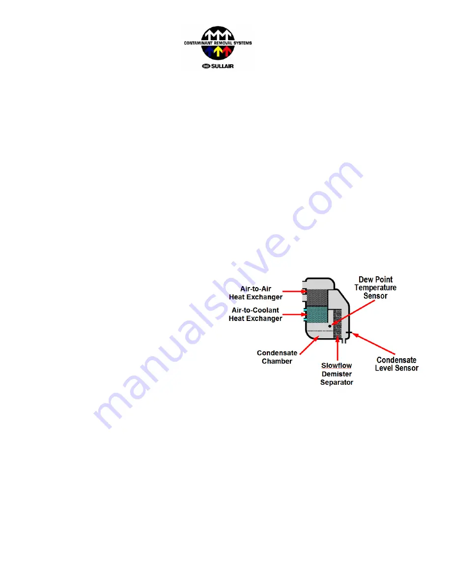
The SRC is unique in that it’s entire air circuit is combined into a single compact 4-in-1 unit,
combining:
•
the Air-to-Air Heat Exchanger,
•
the Air-to-Coolant Heat Exchanger,
•
a Slowflow Demister Separator, and
•
a Condensate Chamber.
into a single component (patent pending).
This combined component performs the functions
of cooling the incoming air to the desired
temperature (using first the cold outgoing air, and
then the coolant), as well as separating the liquid
form the air stream, and collecting the
condensate to drain it from the system*.
A
B
C
The Air-to-Air and Air-to-Coolant heat exchangers are an aluminium fin design, which combine high
surface area (and therefore efficient heat transfer) with low pressure drop and minimum corrosion.
The air circuit is insulated with special TSI Thermal Shield Insulation (polystyrene based) offering a
very high thermal retention for even further improved efficiency.
D
There are two control devices in the Air Circuit
•
the Dew Point temperature Sensor, and
•
the Level Sensor*.
* SRC-400 to 1000 only – see Section 9 for further information.
Page 9 of 56


