Stulz DRH-04 Скачать руководство пользователя страница 8

(April, 2013)

DRH Series GEN1 Ultrasonic Humidifi er Installation, Operation & Maintenance Manual

1-5

1.5 General 

Design

The 

DRH

 Ultrasonic Humidifi er directly atomizes water, producing a fi ne mist. The humidifi er incorporates 

high frequency nebulizers to produce ultrasonic waves, a fan to propel the mist out, and an automatic water 
supply mechanism to maintain the supply water at a constant level. When conducting routine maintenance, it is 
important to clean the air fi lter and water tank because it signifi cantly affects the humidifying capacity and life of 
the ultrasonic nebulizers.

1.6  Main Parts

1.6.1   Ultrasonic Nebulizer Unit

This consists of a modular assembly located in the 
bottom of the water tank incorporating a 1.6Mhz 
power oscillator on and a piezoelectric transducer. 
The transducer vibrates at that frequency, developing 
ultrasonic columnar waves in the water and 
producing a fi ne mist above that column.

1.6.2   Mist  Guide

The mist guide carries the mist off the top of the 
columnar wave and directs it up and out of the 
humidifi er.

1.6.3   High Water Float Switch

For maximum atomization, it is essential the water 
level in the tank be constantly maintained. The High 
Water Float Switch is an input to the Level Controller. 
It is open when the water level is below the optimal 
level and is closed when the water level reaches the 
maximum level. 

1.6.4   Low Water Float Switch

Operating the humidifi er when the water level is 
below the top of the transducers will damage the Ul-
trasonic Nebulizer Unit. The Low Water Float Switch 
is an input to the Level Controller. It is open when 
the water level is near an unsafe level and is closed 
when the water level is at a minimal level.

1.6.5   Fan

The 24VDC fan or fans both lightly pressurizes the air 
above the water to provide a path for the mist to pass 
through the Mist Tubes and provides a sheet of air to 
carry the mist away from the humidifi er into the room. 
The fan is controlled by the Level Controller.

1.6.6   Air  Filter

The Air Filter removes coarse dust from the air and 
prevents the humidifi er water tank from becoming 
dirty which would affect the mist output.

1.6.7   Water Fill Valve Solenoid

The Water Fill Valve Solenoid is a 24VDC solenoid 
that allows water from the water supply to enter into 
the tank when energized by the Level Controller. 
There is an orifi ce to restrict the fl ow of water.

1.6.8   Water Supply Valve

(To be provided by the user)

A valve must be installed upstream from the humidi-
fi er for service and maintenance. The valve must be 
rated for DI water.

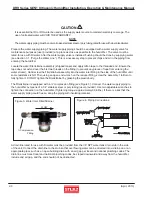
1.6.9   Water Supply Tubing

(To be provided by the user)

Water supply tubing must  be provided to connect the 
water supply to the water fi lter/strainer in the back 
of the unit. The fi lter/strainer is equipped with a ¼” 
compression fi tting. Utilize ¼” stainless steel or poly 
tubing rated for use with DI water.

1.6.10  Drain and Overfl ow Assembly

The Drain and Overfl ow Assembly contains a 24 
VDC drain solenoid valve, an overfl ow pipe and a 
drain outlet. The drain valve solenoid is controlled by 
the Level Controller to drain water from the tank via 
the drain outlet. If the water level in the tank exceeds 
the height of the overfl ow pipe, the excess water is 
diverted to the drain outlet.

1.6.11 Temperature 

Sensor

The temperature sensor monitors the temperature 
of the tank and is read by the Level Controller which 
prevents overheating and freeze protection

Содержание DRH-04

Страница 1: ...April 2013 DRH Series GEN1 Ultrasonic Humidifier Installation Operation Maintenance Manual MODELS DRH 04 DRH 08 DRH 06 DRH 16 READ AND SAVE THESE INSTRUCTIONS LIRE ET CONSERVER CES INSTRUCTIONS...

Страница 2: ...ntains confidential and proprietary information of Stulz Air Technology Systems Inc Distributing or photocopying this document for external distribution is in direct violation of U S copyright laws an...

Страница 3: ...1 3 3 Procedure For Operation 3 1 3 4 Precautions 3 2 3 5 Steps for Long Term Shutdown 3 2 4 0 Maintenance Repairs 4 1 4 1 Periodic General Maintenance 4 1 4 1 1 General 4 1 4 2 Maintenance Items and...

Страница 4: ...mation A bold text NOTE marks a short message in the information to alert you to an important detail A bold text CAUTION safety alert appears with infor mation that is important for protecting your eq...

Страница 5: ...g of the air inlet The humidifier may be filled with the condensed mist and electrical shorts may result CAUTION Observe the unit for water leakage A short circuit could occur if the humidifier is spl...

Страница 6: ...original warranty period or for 90 days from the date of installation whichever is greater Stulz Air Technology Systems Inc s warranty does not cover failures caused by improper installation abuse mis...

Страница 7: ...r supply temperature 40 F to 104 F Parts to be provided by user DI or RO supply water Water supply valve Water supply tubing 1 4 stainless steel or poly tubing rated for DI water power supply wiring a...

Страница 8: ...he water level is near an unsafe level and is closed when the water level is at a minimal level 1 6 5 Fan The 24VDC fan or fans both lightly pressurizes the air above the water to provide a path for t...

Страница 9: ...proportional signal is greater than 10 of the maximum input the microprocessor will turn the Solid State Relay on and off in a pulse width modulation control The period of the pulse width is 1 second...

Страница 10: ...l Avoid dropping or jarring the unit to prevent damage to the internal parts The unit should always be stored in a dry location prior to installation A Data Package has been sent with your unit It con...

Страница 11: ...ht of the unit Weight estimates can be found on the installation drawing provided with your unit Secure the unit with fasteners field supplied by others so that it will not move during operation Ensur...

Страница 12: ...side of the humidifier until some resistance is felt Then using an open end wrench on the reducer fitting screw the assembly 1 full turn to fully tighten it DO NOT tighten the filter strainer by gras...

Страница 13: ...correct electrical wire sizing from the control panel to the humidifiers for three different distances All wire sizes listed are for stranded THHN or NTW wire only Do not use solid conductor wire For...

Страница 14: ...Operation 1 Turn the main power source switch on the control box to the On position 2 Open the water supply valve allowing water to flow to the humidifier 3 Perform a manual drain cycle to flush any...

Страница 15: ...teps for Long Term Shutdown If the humidifier is not signalled to turn On for a period of three days the level control board will automatically signal the humidifier to operate a drain cycle When oper...

Страница 16: ...ch to Off and close the water supply valve WARNING Turn off power to the unit unless you are performing tests that require power With power and controls energized the unit could begin operating automa...

Страница 17: ...Cycle Description Necessary Tools Phillips screwdriver Air filter cleaning About once a week depending on the extent of contamination The interval should be short ened if environmental condi tions are...

Страница 18: ...ontrol box disconnect switch to Off and close the water supply valve 2 Loosen the bowl on the filter strainer assembly and remove it Photo 3 3 Remove the element and rinse the filter and the inside of...

Страница 19: ...cement 4 2 4 Float Switches 1 Loosen and remove the float panel mounting screws 2 Pcs Photo 8 Note Don t let the screws drop into the tank 2 Lift the float panel out and turn it over Photo 9 3 Check f...

Страница 20: ...the air flow guide Photo 13 4 Check the water tank interior for contamination Wipe and clean the water tank interior and clean the surface of the transducers etc in the water tank by wiping with a sof...

Страница 21: ...through the above checking remove the mist guide cover and air flow guide and check the interior of the water tank 4 3 Troubleshooting and Repair Should any failure occur make the necessary repairs re...

Страница 22: ...ply system overflowing Water supply solenoid valve is faulty Overflowing occurs even after power is turned off 4 Consumable parts Fan lead wires are loose or disconnected from the terminals Clean the...

Страница 23: ...ing the parts Photo 19 6 The transducers are visible when you rotate the tank to view the bottom Photo 20 7 The nebulizer print plates are on the side of the tank adjacent to the transducers Photo 21...

Страница 24: ...re ties bundling the sensor cable and unscrew the sensor wires from the terminal connectors on the printed circuit board 3 Connect the new sensor wires to the printed circuit board 4 Install the new s...

Страница 25: ...e the nuts to mount the new part Photo 27 5 Clean the spacer o ring groove and o ring 6 Assemble the new transducer with the spacer and o ring and install them with the saved mounting screws Photo 28...

Страница 26: ...laced it is recommended that the transducer be replaced also 6 Referring to Sect 4 4 2 Re assembling re assemble the unit by reversing the procedure described in Section 4 4 1 4 4 6 Water Solenoid Val...

Страница 27: ...rd remove the lead wire terminal connectors 3 Pcs from the board see Photos 6 7 Note Grasp the connectors when removing Never pull the lead wires 10 Slide the level control board out along the guides...

Страница 28: ...n UPS ground the customer is responsible for the shipping charges If you do not have established credit with STULZ you must give a freight carrier account number A written or faxed purchase order is r...

Страница 29: ...DRAWINGS 6 1 Layout Drawing of Humidifier Covers Removed to Show Parts 1 4 2 8 7 6 5 3 The bubble numbers in the drawing coincide with the item numbers listed below 1 Drain Stub 1 8 NPT 2 Water Supply...

Страница 30: ...L NC NO C L M DC DC SolidState Relay 4 3 X 1 X2 PCB Level Controller X1 2 X1 3 X1 5 X2 1 X2 2 X2 3 X2 4 X2 5 X2 6 X2 7 X2 8 X3 1 X3 2 X3 3 X3 4 X3 5 X3 6 X1 6 X1 7 X1 4 X1 8 From Control Box Nebulize...

Страница 31: ...lve Solenoid DrainValve Solenoid Fan HighLevel Switch LowLevel Switch OverTemp Sensor BLUE RED X1 1 X X 2 1 X 1 X 2 Current ofRelay 5A 10 12A 1 2 2 1 PinNumber 4 X1 2 X1 3 X1 1 X1 4 X1 2 X1 3 X1 Conne...

Страница 32: ...2013 DRH Series GEN1 Ultrasonic Humidifier Installation Operation Maintenance Manual OUD0077D April 2013 DRH Series GEN1 Installation Operation Maintenance Specifictions are subject to change without...

Отзывы: