


(April, 2013)
DRH Series GEN1 Ultrasonic Humidifi er Installation, Operation & Maintenance Manual
2-4
2.5 Main Power And Control Wiring
For wiring, refer to the electrical drawing supplied with your unit to determine the total number of inter-
connecting conductors required for your system and for the proper wire terminations.
For internal wiring of the humidifi er, see the “Electrical Circuit Diagrams”, Section 6.2.
NOTE
Wiring terminations may become loose during transit of the equipment therefore, verify all wiring terminations
are secure prior to operation.
Verify that the main power supply to the control box coincides with the voltage, phase and frequency information
specifi ed on the nameplate. The nameplate also provides the full load amps (FLA), the current that the unit
will draw under full design load, the minimum circuit ampacity (MCA) for wire sizing, and the maximum fuse
size (MFS) for circuit protection. The power source must be provided with a circuit breaker for safety. Ensure a
ground is connected to the unit. The humidifi er is rated to operate with a nominal input of 48VDC. To maintain
warranty coverage, never allow the humidifi er input voltage to exceed 51 volts as damage will occur to the
transducers and print plates.
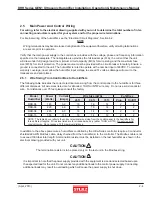
2.5.1 Wire Sizing From Control Box to Humidifi ers
The following table indicates the correct electrical wire sizing from the control panel to the humidifi ers for three
different distances. All wire sizes listed are for stranded, THHN or NTW wire only. Do not use solid conductor
wire. For distances over 75 feet please consult the factory.
Model
Humidifi er
Power
(Watts)
Current
(Amps)
Wire Size (AWG)
# of Wires
25 ft.
50 ft
75 ft.
Prop.
On/Off
DRH-04
145
3.2
16
16
14
2
2
DRH-06
220
4.6
16
16
14
2
2
DRH-08
285
6.0
16
14
12
2
2
DRH-16
565
11.8
16
14
12
2
2
NOTE: The table above refl ects the correct electrical wire sizing from the control panel to the humidifi ers for
three different lengths. Wire sizes listed are for stranded wire only (either THHN or NTW).
Do not use solid
conductor wire
. Do not exceed 75 ft. maximum distance.
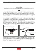
In addition to the above power wires, humidifi ers controlled by the Ultra-Series controller require a 3 conductor
shielded 22 AWG Modbus cable, daisy chained from the humidifi er(s) to the controller. The Modbus cable is not
to exceed 1000 feet total length. A termination resister must be installed on the last humidifi er as shown in the
electrical drawing provided with your unit.
CAUTION
The termination resistor is to be placed only on the last unit in the Modbus string.
CAUTION
It is important to note that the power supply provided with the equipment is sized and selected based upon
the expected load for the unit. Do not connect any additional loads to the control power supply. Connecting
additional loads may result in overloading which will cause the power supply to shut down.