


(April, 2013)
DRH Series GEN1 Ultrasonic Humidifi er Installation, Operation & Maintenance Manual
4-9
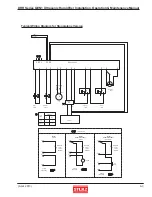
4.4.3 Replacing the Temperature Sensor
The temperature sensor is mounted to either the fi rst nebulizer print plate or on the front of the water tank
depending on when your unit was shipped. Referring to Section 4.4.1, “Preparation for Repairs” steps 1 - 5,
place the water tank on a well lit work surface. Determine the sensor location (see photos 22 and 24). Refer
to section 4.4.3.1 if the sensor is mounted on the nebulizer print plate. Refer to section 4.4.3.2 if the sensor is
mounted on the tank.
25
Terminal
Connector
Nylon
Screw
Sensor
Mica
Pad
Slots
23
Nut
Washer
Shoulder Washer
Sensor
Mica Pad
4.4.3.1
Temperature Sensor on Nebulizer Print Plate
1) The temperature sensor is mounted to the fi rst nebulizer
print plate. Using a 5.5 mm nut driver, remove the mounting
nut holding the sensor in place. Remove the sensor and the
insulating parts. Save the nut and insulating parts to mount the
new sensor.
Photo 22
2) Carefully cut the wire ties bundling the sensor cable and
unscrew the sensor wires from the terminal connectors on the
printed circuit board.
3) Connect the new sensor wires to the printed circuit board.
4) Install the new sensor to the print plate together with the
saved mica pad and insulating parts. Ensure the insulating
bushing is correctly placed to prevent the sensor from shorting
to the mounting stud.
Photo 23
5) Referring to Sect. 4.4.2, “Re-assembling”, re-assemble the
unit by reversing the procedure described in Section 4.4.1.
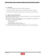
4.4.3.2
Temperature Sensor on Water Tank
1) The temperature sensor is mounted on the front of the tank
near the fl oat switches. Carefully cut the wire tie holding the
sensor cable and remove the nylon screw holding the sensor
in place. Remove the sensor and save the mica pad and nylon
screw to mount the new sensor.
Photo 24
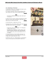
2) Remove the terminal connector from the sensor and connect
it to the new sensor. Ensure the three slots in the terminal
connector are oriented upwards.
Photo 25
3) Install the new sensor to the tank together with the saved
mica pad. Cable tie the sensor cable restrain it.
4) Referring to Sect. 4.4.2, “Re-assembling”, re-assemble the
unit by reversing the procedure described in Section 4.4.1.
22
24