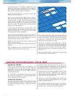
10mm (dia.) holes
Evacuated tubes
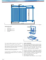
Figure 20
Angle brace
(rear)
Figure 19
Ang
led b
race leng
th
Figure 18
Side brace
M10 screw & nut
Figure 17
Measured distance between mounting slots
Figure 16
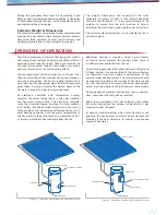
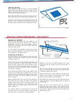
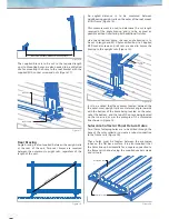
Solarcore Collector Panel Fixture Holes
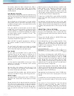
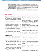
Two 10mm fastening holes are to be drilled through the
base of the solar collector to create a robust connection
to the frame rails (Figure 20).
These holes must be located between the evacuated
tubes on the flat base surface. It is also important that
the holes line up horizontally for a square connection to
the frame rail channel using the supplied socket screws
and rail nuts.
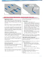
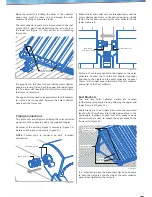
Rear Bracing
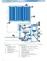
Angle bracing is also required between the upright rails
at the rear of the unit. Two rear braces are required
between the outer-most upright rails, regardless of the
length of the unit.
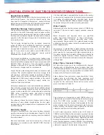
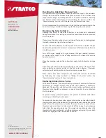
An angled distance is to be measured between
neighbouring upright rails on the outer of the roof mount
tilt kit frame (Figure 18).
This measurement is used to determine the cut length
required of the angle bracing and is to be as great as
possible without interfering with additional fixtures.
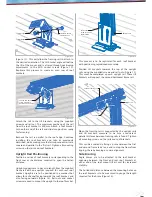
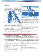
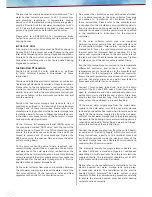
Like the horizontal brace, the rear angle bracing is to
be cut to length and M10 holes drilled on site. Supplied
M10 socket screws and rail nuts are used to secure the
bracing to the upright rails (Figure 19).
It is to be noted that these braces located between the
the outer-most upright rails must always angle inwards
with the bottom of the brace being located on the outer
rail at the bottom, and the top of the brace being located
on the inner rail, as per the example of the dimension
line shown in Figure 18.
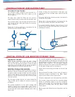
The supplied brace is to be cut to the required length
on site. Mounting holes are also needed to be drilled on
site for mounting the brace to the roof bracket with the
supplied M10 socket screw and nuts (Figure 17).


