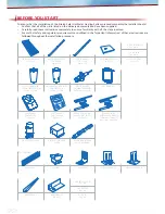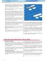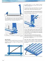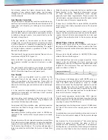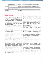
M10 socket screw
(& washer)
M6 TS self-drilling
screw
Angle bracket
(right)
Angle bracket
(left)
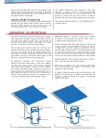
Figure 26
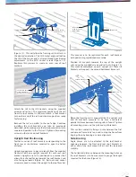
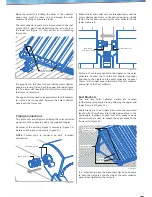
M6 TS self-drilling
screw
Angle brace
M10 socket screw
(& washer)
Rail nut
Collector
Figure 25
Angle Bracket Fastening
Angle brackets are required to secure the top of the solar
collectors to the upper frame rail. These angle brackets
are to be created from the supplied angle bracing by
cutting to a length of approx. 85mm (cut on site).
When both rail nuts are fastened, M6 TS self-drilling
screws are needed to screw the brace to the solar
collector frame.
Two to three screws can be used per brace, with
placement being crucial as to not damage or penetrate
the solar collector flashing or evacuated tubes. The TS
screws are used to drill through the angle brace and to
fasten only to the frame of the solar collector (Figure 25).
Securing a brace at one end will assist in aligning the solar
collector panels and keeping the frame square and will
also stop the solar collector panels from unintentional
movement.
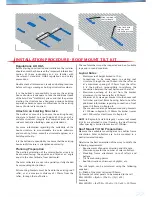
Electronic Controller Position (Indoor)
The electronic controller should be mounted on an inside
vertical surface, where it is protected from moisture and
direct sunlight. A wall in the kitchen or laundry is ideal.
Electronic Controller Position (Outdoor)
The electronic controller should be mounted on an
outside vertical surface, where it is sheltered from direct
sunlight and weather. A wall under the eaves is ideal.
The electronic controller should be mounted at chest
height in a position where it can be easily accessed.
The electronic controller will require a 240V, 10A earthed
power point.
IMPORTANT NOTE
The controller is factory programmed to the correct
settings. These settings must not be altered.
To ensure frost protection the power must remain connected
to the electronic controller and circulation pump.
Installation Procedure
The mains power supply lead, circulation pump power
lead, hot temperature sensor lead and cold temperature
sensor lead are connected to the electronic controller.
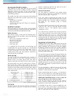
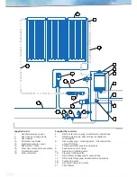
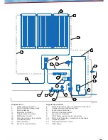
The system installation diagrams shown in Figure 29 and
Figure 30 detail the general arrangement of components,
plumbing and wiring.
Please refer to the manufacturer’s instructions for the
electronic controller installation and wiring connection
details. Failure to follow the manufacturer’s instructions
may cause failure of the electronic controller and will
void the warranty.
IMPORTANT NOTE (INDOOR CONTROLLER)
The second storage sensor TT and electric boost heating
element are not connected to the electronic controller.
INSTALLATION OF ELECTRONIC CONTROLLER
A 10mm hole (dia.) must also be created on site on the
appropriate face of each bracket (Figure 26).
Each solar collector attached to the mount requires both
a left and right bracket to affix the panel to the unit.
The angle brackets are to be pushed hard against both
the outer of the framing rail and also the inside face of
the solar collector frame, then tightly fastened to the
back of the frame rail using the supplied M10 socket
screws and rail nuts.
When all brackets have been fastened into place, M6 TS
self-drilling screws are used to drill through the bracket
and into the solar collector frame, subsequently fastening
the panels to the top rail (Figure 26).
The area of the solar collector frame to drill through is
slight and the installer must be sure not to damage the
solar collector when fastening.

