to 50°C or 45°C where the hot water is supplied to
areas used for personal hygiene such as bathrooms and
ensuites. Please refer to AS/NZS3500.4 for temperature
limits for facilities such as child minding centres, schools
and nursing homes.
IMPORTANT NOTE
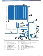
A hot water non-return valve must be fitted as shown in
Figures 29 & 30 to prevent hot water flowing to the cold
inlet of the tempering valve during stagnation conditions.
Failure to fit this non-return valve can result in excessive
tank noise or scalding when a hot tap is opened during
stagnation conditions.
Installation Procedure
Position and install the solar collectors as outlined
in “Solar Collector Position & Orientation” of these
instructions.
Position and install the electronic controller as outlined in
“Installation of Electronic Controller” of these instructions.
Please refer to the manufacturer’s instructions for the
electronic controller installation and wiring connection
details. Failure to follow the manufacturer’s instructions
may cause failure of the electronic controller and will
void the warranty.
Position the hot water storage tank (and safe tray
if required) as outlined in “Hot Water Storage Tank
Location” within this section of these instructions. Please
refer to the manufacturer’s instructions for the hot water
storage tank installation details. Failure to follow the
manufacturer’s instructions may cause failure of the hot
water storage tank and will void the warranty.
Using the brackets provided, mount the gas booster on
the hot water storage tank (only if positioned outside) or
on an outside wall as outlined in “Gas Booster Location”
within this section of these instructions. Please refer
to the manufacturer’s instructions for the gas booster
installation details. Failure to follow the manufacturer’s
instructions may cause failure of the gas booster and will
void the warranty.
Fit a suitable disconnection union and isolation valve to
the gas inlet of the gas booster and connect to the gas
supply. Please refer to “Gas Supply” within this section of
these instructions for gas supply details. Purge the gas
supply lines before final connection to remove air and
swarf. Test for gas leaks.
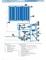
Fit the 15mm Pressure & Temperature Relief (P&TR) valve
to the connection marked “P&TR valve” near the top of
the tank. Use Teflon thread tape and ensure the tape
does not protrude past the end of the thread to prevent
risk of valve blockage. Tighten the P&TR valve using the
spanner flats and leave the valve outlet pointing down.
Fit the pressure limiting valve (where required), non-
return/isolating valve/strainer, expansion control valve
and tee to the cold water inlet connection at the bottom
of the hot water storage tank. A pressure limiting valve
is required if the water supply pressure exceeds 500kPa.
Fit the solar collector flow pipe and insulation between
the cold water supply pipe tee and the water and
insulation inlet of the first solar collector. Fit the solar
assembly non-return valve to the outlet of the circulation
pump.
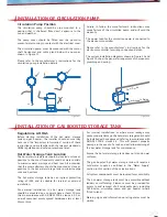
Pipe mount the circulation pump, with valves attached,
at a suitable location in the solar collector flow pipe as
outlined in “Installation of Circulation Pump” of these
instructions.
Please refer to the manufacturer’s instructions for the
circulation pump installation details. Run the circulation
pump power cable to the electronic controller and connect
it to the pump terminals specified in the manufacturer’s
instructions for the electronic controller.
Fit the solar collector return pipe and insulation
between the water outlet of the last solar collector and
the connection marked “solar return” on the hot water
storage tank.
Cover the cold temperature sensor with thermal paste
for improved heat conduction. Fit the cold temperature
sensor into the immersion sleeve at the bottom of the
tank and seal with silicon.
Run the cold temperature sensor lead to the
temperature differential controller and connect it to
the cold temperature sensor terminals specified in
the manufacturer’s instructions for the temperature
differential controller. Ensure the cold temperature
sensor lead is not in contact with the hot water pipes
at any point and fasten to framework with cable ties as
necessary.
Connect 15mm copper tube drain lines to the drain
outlets of the ECV and P&TR valves. Drain lines must be
open to atmosphere and slope continuously down to a
visible drain point, preferably over a drain. Drain lines
must be less than 9 metres long, free of restrictions and
other valves and positioned to prevent freezing.
Fit the mains water supply pipe from the mains water
supply to the cold water inlet of the hot water storage
tank and purge before final connection to remove air and
swarf.
Fit Dn20 copper tube and 20mm thick insulation between
the hot water outlet of the hot water storage tank and
the cold water inlet of the gas booster.
Fit the hot water supply pipe from the hot water outlet
of the gas booster to the pipe supplying hot water to
the building. A temperature limiting device is required as
outlined in “Water Pipes, Valves and Fittings” within this
section of these instructions. The installation of the gas
boosted Stratco Solarcore
TM
hot water heating system is
now complete.
Please follow the commissioning procedure in
“Commissioning” of these instructions carefully to ensure
the gas boosted solar hot water heating system functions
correctly.

