background image

General  

Preliminary 

Service Manual MARINE 2012 

Z001138-1_2013-02-01


46/65


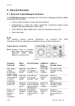
readjust 

Devices or tools 


refill 

Adding and replenishing of operating agents 


renew 

Replacing an auxiliary material by a new one 

Corrosion protection 
agent, sealing 
material, paint 

gauge 

Reading in actual positions in programming 
memory 


replace  

Exchanging of a device, a main assembly, an 
assembly or a component by the same, new or 
repaired ones 


measure 

Steps taken to determine the actual status by 
evaluating of physical entities 


check 

Steps taken to compare the actual status with a 
determined 

Valve lift, piston 
diameter, valve 
clearance, close fit, 
V-belt tension 

clean  

Removal of foreign and auxiliary material  


maintain 

Steps taken to keep the respective determined 
planned status 


Fasten 

To secure an element with a bolt and tighten to 
specified torque. 

Bracket fastened to 
engine 


Содержание Marine Engine 2012 Series

Страница 1: ... Z001138 1_2013 02 01 STEYR TURBO DIESEL ENGINES Steyr Marine Engine Family 2012 SERVICE MANUAL Z001138 0 1st Edition February 2013 STEYR MOTORS GmbH www steyr motors com Im Stadtgut B1 A 4407 Steyr Gleink AUSTRIA ...

Страница 2: ...General Preliminary Service Manual MARINE 2012 Z001138 1_2013 02 01 2 65 THIS PAGE IS INTENTIONALLY BLANK ...

Страница 3: ...Marine Engine Family 2012 to maintain their operating safety and reliability To achieve continuous improvement with regard to form and contents of the information required we are assigned to your aid We therefore would much appreciate your comment to following questions Which descriptions or terms are not understandable Which supplements or completions do you propose Where did creep in contents re...

Страница 4: ...ted at a later date of such change Illustrations in this manual may not always correspond to actual implements or components and are mainly intended as reference STEYR MOTORS GmbH reserves the right to make changes at any time without notice on technical data or models and or to discontinue models The right is also reserved to change technical data or components at any time without incurring any o...

Страница 5: ...65 Z001138 1_2013 02 01 TABLE OF CONTENTS MAIN ASSEMBLY GROUP ENGINE GENERAL 01 ENGINE 02 COUPLING 03 FUEL SYSTEM 04 EXHAUST SYSTEM 05 COOLING SYSTEM 06 ELECTRICAL EQUIPMENT 14 HYDRAULIC PUMP 22 ENGINE PREHEATING ...

Страница 6: ...3 Flywheel 01 04 Piston Rings and Pin Connection Rod 01 05 Camshaft Housing 01 06 Oil pump Oil pipe Oilcan 01 08 Page 1 2 Intake Manifold Exhaust Manifold 01 13 Oil cooler Filter 02 Coupling 02 00 Fly Wheel housing 02 01 Ring Gear Carrier and Flex Plate 03 Fuel System 03 02 Unit Injector Fuel Pump 03 05 Turbocharger 03 08 Contr Solenoid Inj Timing Device 03 09 Fuel Filter 03 11 Glow Plug ...

Страница 7: ...System 05 03 Water pipe Thermostat 05 04 Water pump 05 05 Fan Assy 05 06 Page 1 2 Drive Belt Pulleys Tensioner Belt 1 2 06 Electrical System 06 01 Alternator Bracket 06 03 Starter 06 05 Engine Harness 06 06 Harness ECU 14 Hydraulic pump 14 08 Hydraulic pump 52 Air Conditioning 52 00 A C Compressor ...

Страница 8: ...General Preliminary Service Manual MARINE 2012 Z001138 1_2013 02 01 8 65 VERSIONS OF MANUAL Version Date Modification 1 0 01 02 2013 New edition ...

Страница 9: ...iagnostic system 37 D 3 Operation after Break In 42 D 4 Extended Storage Preservation Procedure 42 E Quality guidelines for repair 44 E 1 Spare part specification 44 E 2 Workshop Profile 44 E 3 Nomenclature 45 E 4 SI System 47 E 5 Abbreviations 48 F Operating material and information on disposal 49 F 1 List of operating material 49 F 2 Disposal of automotive waste products 50 G Notes on safety 51 ...

Страница 10: ...61 H 6 Solvent free sealing materials 61 I Wear Limits 64 I 1 Adjustment information for service and maintenance 65 I 1 1 Engine timing measured with dial indicator No 2300899 0 65 I 1 2 Tension timing belt measured with tool VR00515 0 65 I 1 3 Start of fuel delivery on the unit injectors measured with dial indicator No 2300899 0 65 I 1 4 Valve clearance measured with tool No 2300712 3 65 ...

Страница 11: ... 65 Z001138 1_2013 02 01 A GENERAL REMARKS A 1 Model and Serial Number The primary model and serial number is located on the engine as illustrated These numbers are required for warranty claims and ordering parts ...

Страница 12: ...logue SE126E25 P N Z011841 0 spare parts catalogue SE156E26 P N Z011842 0 spare parts catalogue SE196E35 P N Z011843 0 spare parts catalogue SE236E40 P N Z011844 0 spare parts catalogue SE236S36 P N Z011845 0 spare parts catalogue SE266E40 P N Z011846 0 spare parts catalogue SE266S36 P N Z011847 0 spare parts catalogue SE286E40 P N Z011848 0 spare parts catalogue SE306J38 P N Z011849 0 Optional eq...

Страница 13: ... 170 190 190 205 215 rated speed rpm 2500 2600 3500 4000 3600 4000 3600 4000 3800 full power speed range rpm 2175 2550 2350 2650 3050 3550 3550 4100 3350 3650 3550 4050 3350 3650 3500 4100 3600 3850 max torque Nm 390 450 445 470 540 530 600 570 588 max torque lb ft 288 360 328 347 398 391 443 420 434 Speed at Maximum Torque rpm 1800 1800 2050 2550 1800 2300 1800 2550 3300 Maximum test speed rpm 25...

Страница 14: ... 5 89 8 85 9 96 3 mean effective Pressure bar 13 2 15 9 15 0 15 9 17 7 17 8 19 8 19 2 21 2 specific power lbs HP 6 26 5 01 3 94 3 24 3 24 2 90 2 90 2 69 2 56 dry weight kg 340 340 340 340 340 340 340 340 340 specific power kg PS 2 84 2 27 1 79 1 47 1 47 1 32 1 32 1 22 1 16 idle speed rpm 630 630 630 630 630 630 630 630 630 aspiration TCA TCA TCA TCA TCA TCA TCA TCA TCA turbo system WG WG WG geom V...

Страница 15: ...50 30 50 30 50 30 50 30 50 spec fuel consumption at rated power g kWh 228 230 240 249 240 249 243 248 243 min spec fuel consumption g kWh 205 205 205 210 202 205 205 210 210 compressor outlet temperature at rated power C 130 140 145 200 160 165 175 180 180 boost pressure adjustment value 1mm deflection mbar 1680 1680 1880 geometrical turbocharger electronic controlled 1920 electronic controlled 20...

Страница 16: ...0 2800 3550 3050 4000 3300 3800 3800 compression ratio ε 17 0 ε 17 0 ε 17 0 ε 17 0 ε 17 0 ε 17 0 ε 17 0 ε 17 0 ε 17 0 max exhaust backpressur e mbar 150 150 150 150 150 150 150 150 150 backpressur e tolerance mbar 0 50 0 50 0 50 0 50 0 50 0 50 0 50 0 50 0 50 max engine cooling water outlet temp C 81 83 83 85 86 86 86 86 87 exhaust gas temperature C 375 445 480 415 506 510 535 510 525 oil sump temp...

Страница 17: ... 0 67 0 8 0 8 0 8 0 8 0 8 0 75 Tension timing belt N 600 30 600 30 600 30 600 30 600 30 600 30 600 30 600 30 600 30 unit injector opening pressure kPa 26000 36000 kPa 26001 36000 kPa 26002 36000 kPa 26003 36000 kPa 26004 36000 kPa 26005 36000 kPa 26006 36000 kPa 26007 36000 kPa 26008 36000 kPa UI adjustment mm 9 20 9 10 8 85 8 85 8 74 8 65 8 74 8 70 8 65 UI adjustment tolerance 0 02 0 02 0 02 0 02...

Страница 18: ... 0 02 3 59 0 02 valve clearancy mm 0 25 0 25 0 25 0 25 0 25 0 25 0 25 0 25 0 25 0 25 0 25 0 25 0 25 0 25 0 25 0 25 0 25 0 25 RCD EU 94 25 EC 2003 44 EC without integral exhaust X X X X X X X X X Bode nsee BSO II Bodensee BSO II Doppelinst Commercial EU 97 68 EG 2004 26 EG X X X X X X X X X EPA Tier III US IMO Nox Cert Nr MED B 5675 X X X X X X X X X Performance Rating PR INT MCD PR INT MCD PR INT ...

Страница 19: ...önig 2181025 0 Tarabusi 2181146 0 König piston bowl 2179531 3 2179531 3 2179531 3 2179531 3 2179531 3 2179531 3 2179531 3 2179531 3 2179531 3 Fuel delivery pump 2173396 6 2173396 6 2173396 6 2173396 6 2173396 6 2173396 6 2173396 6 2173396 6 2173396 6 fuel delivery pump name 12V TI Automotive 12V TI Automotive 12V TI Automotive 12V TI Automotive 12V TI Automotive 12V TI Automotive 12V TI Automotive...

Страница 20: ...180569 0 2180569 0 2180569 0 2180569 0 2180569 0 2180569 0 starter 2040077 1 2040077 1 2040077 1 2040077 1 2040077 1 2040077 1 2040077 1 2040077 1 2040077 1 Max Amp consumption 20 C 240 240 240 240 240 240 240 240 240 Min Starting RPM flywheel description 2180676 0 2180676 0 2180676 0 2180676 0 2180676 0 2180676 0 2180676 0 2180676 0 2180676 0 flywheel torque of inertia kgm 0 1446 0 1446 0 1446 0 ...

Страница 21: ... 0427 0 0427 propeller information 3 4 17 19 Inch 3 4 17 19 Inch 3 4 17 19 Inch 3 4 17 19 Inch 3 4 17 19 Inch 3 4 17 19 inch 3 4 17 19 inch 3 4 17 19 inch 3 4 17 19 inch Turbo Charger no 2203505 0 2203505 0 2205034 5 2173969 0 2201765 0 2181154 0 2201765 0 2179202 0 2179202 0 Exhaust manifold 2179798 0 2179798 0 2179798 0 2179798 0 2179798 0 2179798 0 2179798 0 2179798 0 2179798 0 Electr Control M...

Страница 22: ...Drive Belt Raw Water Pump 23 Engine Mount 24 Drive Belt Tensioner 25 Cover T Belt Lower 26 Vibration Damper 27 Speed Sensor 28 Cover T Belt Upper 29 Cover Rear 30 Valve Cover 31 Heat Exchanger 32 Coolant Expansion Tank 33 Cooler Cap 34 Diagnostic Outlet 35 Inversion Switch 36 Connector Instrument Panel 37 Coolant Temperature Sensor 38 Thermostat Housing 39 Hydraulic Oil Tank 40 Circuit Breakers 41...

Страница 23: ...l Fuel quality is an important factor in obtaining satisfactory engine performance long engine life and acceptable exhaust emission levels Direct injected diesel engines are designed to operate on most diesel fuels marketed today In general fuels meeting the properties of CEC RF 03 A 84 have provided satisfactory performance The ASTM D 975 specification however does not in itself adequately define...

Страница 24: ...tillation 250 C 350 C End point 360 C V V V V 85 65 95 EN ISO 3405 Flash point C 55 EN ISO 2719 CFPP Cloud point C 5 s 15 w Viscosity Kinematic 40 C mm s 2 4 50 EN ISO 3104 Sulphur content mg kg 10 0 EN ISO 20846 EN ISO 20884 Cupper corrosion Rating Class 1 Class 1 EN ISO 2160 Carbon residue Conradson number 10 residue m m 0 30 EN ISO 10370 Ash m m 0 01 EN ISO 6245 Water content mg kg 200 EN ISO 1...

Страница 25: ...ctory fill is a high quality break in oil specified ACEA E7 E9 SAE 10W 40 During the break in period 20 hours frequently check the oil level Somewhat higher oil consumption is normal until piston rings are seated The oil level should be maintained between the minimum and maximum marks on the dipstick The space between the marks represents approximately 2 quarts 2 litres For oil dipstick location r...

Страница 26: ...on on and check for leaks Fuel pump may be defective Replace fuel Replace or drain water from fuel filter Check fuel supply for water contamination If water is present drain fuel tank and flush with fresh fuel Check Engine Management System display for service code Charge or replace battery Starter won t crank 1 Battery connections loose or corroded 2 Battery is dead 3 Starter connections loose 4 ...

Страница 27: ...k Performance loss 1 System error or failure 2 Fuel incorrect 3 Throttle not fully open 4 Overheating Check Engine Management System display for service code Engine coolant temperature audible alarm Fill tank with correct fuel Check fuel filter and fuel flow condition Check throttle command lever for full travel Check cooling system ...

Страница 28: ...gh Blow By unstable engine running Incorrect start of fuel delivery excessive discharge of coolant filler cap overheating coolant system leak of gasket watercooled turbine housing exhaust manifold cylinder missing raw water supply leaking copper insert or o ring leaking oil cooler unit injector o ring Electrical System low battery Overdischarge Connection failure Terminal Main Cable Battery Main S...

Страница 29: ... difficult starting High Blow By unstable engine running Incorrect start of fuel delivery excessive discharge of coolant filler cap overheating coolant system leak of gasket watercooled turbine housing exhaust manifold cylinder missing raw water supply leaking copper insert or o ring leaking oil cooler unit injector o ring Breakdown of injection pump no hydraulic pressure to build up stuck unit in...

Страница 30: ... Clean out desposits in pipelines change zinc anodes If sacrificial progress reaches a material corrosion of 50 Air Filter Check contamination Change air filter element Preserve After season Fuel System Check for leakage hoses prefilter Change fuel filters prefilter Preserve fuel system After season Battery Battery acid level density Electronics Check connections After season Electrical Equipment ...

Страница 31: ...900 hours set point Every 900 hours tighten torques Every 900 hours For Commercial use only unit injector adjustment 300 hrs Hydraulic Pump Check oil level for leakage Change hydraulic oil ATF Every 900 h or every 24 months Gearbox Sterndrive Check oil level for leakage Change gear oil ATF See Manufacturer s specification oil filter Torsional Coupler Check Tightness of bolts Every 48 months Change...

Страница 32: ...E 2012 Z001138 1_2013 02 01 32 65 refer to manufacturer specification drain clean water from separator bowl NOTE Oil exchange interval must be adapted acc application and utilisation of vehicle respectively quality of engine lubricant in use ...

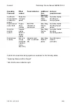
Страница 33: ...Instrument panel maybe different on actual vehicle Operating Parameter Effect noticed Panel Indication Additional Tool Readings Action or possible reason High engine coolant temperature limit exceeded Reduction of engine speed Horn ON 2x p sec Gauge reading 107 C Steyr Diag Power limitation See table trouble shooting Cooling system Defect engine coolant sensor or sensor connection Reduction of eng...

Страница 34: ... stops running NO RPM indication in tachometer Steyr Diag Service code See table trouble shooting Speed sensor Governor position system Irregular engine speed or stalled engine Steyr Diag Service code See table trouble shooting Governing system During break in phase MIL ON at high accelerato r position more than 75 Indication light MIL is swichted ON Steyr Diag Break in phase See information break...

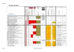
Страница 35: ...General 35 65 Z001138 1_2013 02 01 Trouble Indication ...

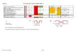
Страница 36: ...General Preliminary Service Manual MARINE 2012 Z001138 1_2013 02 01 36 65 ...

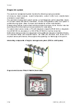
Страница 37: ...xisting active failures remain stored until the problem has been solved Service code has been cleared from the memory to receive actual error code status To select stored service codes a PC with diagnostic program VR00134 0 or diagnostic tool VR00135 1 is necessary or a SCC P No 2179497 0 must be connected Malfunction during operation is categorised in three different categories intermittent failu...

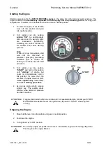
Страница 38: ...ressure glow plug pre heating indication light is turned off before you continue with the start procedure 3 Turn ignition key into position START and hold in this position until starting of engine but under no circumstances hold in this position for more than ten seconds If engine does not start release ignition key momentarily and repeat starting procedure 4 As soon as engine starts release ignit...

Страница 39: ...weather the combined light for glow plug preheating engine oil pressure will not extinguish after 0 7 sec glow plug preheating phase In this case start engine immediately after the light extinguishes 2 Ignition ON before starting Indication memorized service codes 3 Engine running after start Normal condition Note For further information see Table Error indication on Instrument Panel ...

Страница 40: ... NOTE DO NOT RUN ENGINE AT A CONSTANT RPM FOR LONGER PERIODS DURING THIS INITIAL TWO HOURS OF BREAK IN Attention Warning indication engine over load during break in via ECU The ECU controls during the first two hours of engine operation the load on the engine and alarms the drive by the Check Engine Light if much power is demanded from the new engine Illustration represents an example which may di...

Страница 41: ...g by means of dipstick If necessary add oil DO NOT OVERFILL In case that the oil pressure control lamp would illuminated check for correct oil level have the engine checked by your STEYR Service dealer as to malfunction of signal or oil pump NOTE During normal operation of engine oil pressure will rise as RPM increases and fall as RPM decreases In general oil pressure will be higher with cold moto...

Страница 42: ...for future refill and usage 4 Mount brand new oil filter on the engine 5 Fill in preservation oil Shell Ensis Engine Oil 30 part number Z050323 0 5litres to the minimum mark on the dip stick 6 Connect the fuel system to a tank or canister filled with Shell oil V1404 part number Z010014 0 5 liters See ill 1 7 Restart the engine and run for 5 minutes in idle speed or max up to 1500rpm 8 Disconnect t...

Страница 43: ...bad smell 15 Store engine again as in the condition delivered from STEYR MOTORS 16 The engine is now preserved for one more year This preservation procedure must be done every year and ensures that all of the air ways systems raw water systems oil system and the cylinders are protected against corrosion This procedure is repeatable up to a maximum of three times giving a shelf life of up to four y...

Страница 44: ...ty of 5 000 N 500 kg minimum Cleaning device wash basin for soiled components Commercial tools Appropriate test and measuring equipment Receptacles for operating agents Depending on the repair step to be carried out the tools indicated in the STEYR MOTORS TOOL catalogue have to be used Furthermore special care is to be taken in case of purchasing and stock of required operating material spare part...

Страница 45: ... Placement of a component with press fit to another unscrew Opening of turn able locks tighten Closing of turn able locks disassemble 2 x Removal of an assembly from a main assembly or a component from an assembly if other assemblies have been removed before assemble 2 x Putting on an assembly to a main assembly or a component of an assembly if further assemblies are put on for functional achievem...

Страница 46: ...ng of a device a main assembly an assembly or a component by the same new or repaired ones measure Steps taken to determine the actual status by evaluating of physical entities check Steps taken to compare the actual status with a determined Valve lift piston diameter valve clearance close fit V belt tension clean Removal of foreign and auxiliary material maintain Steps taken to keep the respectiv...

Страница 47: ...ergy J Joule kW h kilowatt hour Volume m3 cubic meter cm3 cubic centimetre dm3 cubic decimetre mm3 cubic millimetre l litre Power kW kilowatt Mass t metric ton kg kilogram g gram Temperature K degrees Kelvin C degrees Celsius Energy N Newton kN kilo Newton daN deka Newton Time h hour min minute s second Electricity A ampere V volt W ohm μF microfarad Velocity km h kilometre per hour m s meter per ...

Страница 48: ...n copper main assembly maximum top dead center POWER TAKE OFF power transmission at front of crankshaft end Wrench Size Electronic Management System Electronic Control Unit extender ECU Electronic Management System for DPF Minimum Bottom Dead Centre Diesel Particulate Filter Exhaust Gas Recirulation Diesel Particulate Filter Control Unit Absolut pressure sensor parametric ...

Страница 49: ...rtridge 9000019 1 1 construction adhesive 620 50ml flask 9000017 1 1 construction adhesive 262 50 ml flask Z010207 0 1 contact grease 100 ml tube Z010226 0 1 corrosion protection spray 400 ml can Z010227 0 1 corrosion protection wax 120 ml can Z010084 0 1 grease STRABURAX NBU4 1 kg can Z010205 0 1 fuel rust protection additive 5 lt can 9000197 0 1 electric contact spray Z011627 0 1 silver varnish ...

Страница 50: ... 2100 refers to the required disposal in Austria Respective legal local regulations are to be followed The maintenance and repair personnel has to take care that operating material and other material to be regarded as special waste product is always deposited at collection site Key No Description 31 423 Oil contaminated soil or oil bonding agent 54 102 Waste oil 54 104 Fuels 54 202 Lubricants 54 2...

Страница 51: ...General 51 65 Z001138 1_2013 02 01 G Notes on safety ...

Страница 52: ...G 2 Guidelines for damage prevention The general knowledge and training of the workshop personnel and the contents of the general regulations of safety technology and machine safety regulations Maschinen Sicherheitsverordnung MSV are not subject of this chapter Inappropriate behaviour and insufficient knowledge of hazard during repair works may cause injury to persons In the description of repair ...

Страница 53: ...bonding agent and to be disposed ATTENTION In order to prevent health hazards take care of the following Avoid direct contact with dangerous operating material as far as possible Change clothes as quickly as possible if they are soiled with dangerous operating material Do not keep oily rags in work clothes Clean oil soiled body parts only with products friendly to skin never use rubbing sand or so...

Страница 54: ... 2 2 step 25 Nm 1 Tighten screws of camshaft housing in two steps in precedence of numbering on bearings from the inside outwards Plug screw for locking pin In engine housing 50Nm 5 Connecting rod screws apply oil to thread and screw head support 1 Step 10 Nm 1 2 Step 30 Nm 3 3 Step 75 4 Main bearing screws apply oil to thread and screw head support 1 Step 35 Nm 3 2 Step 45 4 3 Step 45 4 ...

Страница 55: ... apply oil to thread and screw head support M12x90 Allen screw 135 Nm 7 Note re assure tightness of bolts and check screw torque settings a second time copper paste M10x30 75 Nm 5 screw quality 10 9 Note Use Loctite 243 Screw rear ring carrier use LOCTITE 243 on thread 1 step 8 Nm 1 2 step 28 Nm 3 Nut camshaft sprocket taper degreased on camshaft thread lubricated 1 step 80 Nm 4 2 step 240 Nm 12 ...

Страница 56: ...eliminary Service Manual MARINE 2012 Z001138 1_2013 02 01 56 65 Screw tooth belt tensioner 45 Nm 4 Valve adjustment element 55 Nm 3 Screw linkage lever CAUTION left hand thread 7 Nm 0 5 Stud unit injector 21 Nm 2 ...

Страница 57: ...5 Z001138 1_2013 02 01 Collar nut for unit injector 18 Nm 2 Nut adjustment screw of unit injector 30 Nm 3 Plug screw for control rack in camshaft housing 50 Nm 5 Hex flange nut exhaust manifold 28 Nm 2 Copper paste ...

Страница 58: ...MARINE 2012 Z001138 1_2013 02 01 58 65 Exhaust turbocharger A 23 Nm 2 B 50 Nm 5 greased with NEVER SEEZ C 23 Nm 2 Screws intake manifold 28 Nm 2 Engine oil cooler A 12 Nm 2 B 15 Nm 2 Crankcase ventilation A 23 Nm 2 B 9 5 Nm 1 C 3 5 Nm 1 ...

Страница 59: ...General 59 65 Z001138 1_2013 02 01 Thermostat A 9 5 Nm 1 Water pump A 23 Nm 2 B 9 5 Nm 1 AC Compressor optional A 45 Nm 4 B 23 Nm 2 C 9 5 Nm 1 D 45 Nm 4 LOCTITE 243 Alternator ...

Страница 60: ...rial standard and are applicable if no specific torques are indicated For studs tightening torques are to be reduced by 50 If the tightening torque of a screw connection is not reached the tightness of the screw nut Is too low or the ratio of friction do not correspond In any case the screw nut is to be replaced μ tot total frictional value ...

Страница 61: ...y Anaerobic sealing materials These are used for securing fixing and sealing and only harden under exclusion of air Solvent containing sealing materials Due to their contents of volatile parts a loss of volume occurs during hardening During repair the hardening time is taken into consideration If such sealing materials are used special reference is made in the description of the workshop manual H ...

Страница 62: ...crew connections Fixing procedure In general the application of the epoxy to the screw thread is sufficient If screws are screwed into socket threads only the thread bore is wet in order to let the air escape during screwing in Screws or nuts which are tightened with a specified torque are slightly oiled on their support surface or housing part Guidelines for fixing B Designation BM Fixing medium ...

Страница 63: ...ite 5182 Loctite 5900 Loctite 5910 Hand tightness reached after 15 30 min 15 30 min 5 10 min 0 5 48 h 30 min 30 min Functional tightness reached after 1 h 1 h 1 h 0 5 h 2 h 2 h Final tightness reached after 3 h 3 h 4 h 48 h 3 h 3 h SMO Part No 9000059 1 9000017 1 9000019 1 9000297 0 9000298 1 9000510 5 Bottle Vol 10 ml 50 ml 50 ml 315 ml 300 ml 50 ml ...

Страница 64: ...ing 0 25 0 40 0 25 0 40 0 20 0 40 0 75 0 75 0 75 Axial play 1 ring Axial play 2 ring Axial play 3 ring 0 077 0 127 0 07 0 102 0 03 0 065 0 25 0 25 0 15 Camshaft radial Camshaft axial 0 034 0 075 0 096 0 230 0 20 0 50 Valve guide 7 000 7 015 0 15 indicates gauging depth up to 3 mm before end of valve guide Oil pressure idle run Oil pressure rated speed 0 6 1 5 4 0 0 7 0 50 3 00 Backlash of teeth oi...

Страница 65: ...ng belt tension measurement is not within the specified limits of 630 N to 490 N than the settings needs to be readjusted to the specified value I 1 3 Start of fuel delivery on the unit injectors measured with dial indicator No 2300899 0 Setting instruction For original settings on your engine please see table 03 02 06 Maintenance instruction In case the measurements are not within the specified l...

Страница 66: ...01 05 Replace stud bolt for unit injector 34 01 01 06 Replace dowel pin for positioning of unit injector 35 01 01 07 Replace dowel pin for positioning of camshaft housing 36 01 01 08 Replace O ring at oil entry to block 37 01 01 09 Mount frame seal 38 01 02 Crankshaft Bearing Vibration Damper 40 01 02 01 Replace crankshaft 40 01 02 02 Replace gear for oil pump drive 44 01 03 Flywheel 45 01 03 01 R...

Страница 67: ...2 Replace rear ring carrier 69 01 06 03 Replace rear radialshaft sealing ring 70 01 06 04 Replace oil pump front ring carrier 71 01 06 05 Replace oil suction pipe oil return pipe 73 01 08 Intake Manifold Exhaust Manifold 74 01 08 01 Remove intake manifold 74 01 08 02 Mount intake manifold 76 01 08 03 Disassemble exhaust manifold complete with turbo chargers 77 01 08 04 Mount exhaust manifold 78 01...

Страница 68: ...ning away leaking o ring at unit injector leaking oil cooler raw water entry through exhaust system black smoke emission white smoke emission blue smoke emission fuel oil streaks on water surface thermostat stuck open Check cylinder leckage rate valve piston ring Too much oil in the oil pan oil level too high Faulty valve clearance Faulty engine timing valve timing Excessive delay in injection tim...

Страница 69: ...Engine Z001138 1_2013 02 01 4 87 Kapitel MOUNT BRACKET COVER T BELT GASKET SET ...

Страница 70: ...housing cover 01 00 02 Special tool for vibration damper screws No 2300700 0 Locking pin No 2300551 2 1 Unscrew Allen head plug screw ill 1 SW10 2 Turn crankshaft by means of Allen socket size 10 mm until roller of rocker arm cylinder 1 runs up the ramp of injection cam ill 3 3 Insert locking pin 2300551 2 into guide hole and slightly press it against counter weight land of crank shaft ...

Страница 71: ...sealing ATTENTION Prior to starting make sure that Locking pin has been removed 2 Clean sealing surface of camshaft housing and camshaft housing cover Check seal for hardening and damage Exchange if necessary See 01 00 02 3 Remaining assembly is done in reserve order Explanation for engine timing If the crankshaft has been locked in position as described piston cylinder in TDC the following positi...

Страница 72: ...The marked tooth of the camshaft timing belt sprocket stays in line with the upper edge sealing surface of the camshaft housing The notch on the timing belt sprocket of crankshaft is opposite to the arrow marker on the oil pump housing ...

Страница 73: ... cover 3 Release camshaft housing cover sealing by means of screwdriver and remove 4 Clean sealing surface of camshaft housing and camshaft cover carefully 5 Position new seal on camshaft housing cover and press it with the thumb into the groove beginning at the half moon section ill 2 6 Put camshaft housing cover onto camshaft housing Tighten with 14 hexagon screws SW 10 with a torque of 9 5 Nm 0...

Страница 74: ...oosen hexagon screws SW10 remove timing belt covering NOTE See for arrows markings on used timing belt mark timing belt if necessary Consider change intervals see chart maintenance Special tool dial gauge rail 2306031 6 dial gauge digital 2300899 0 probe pin 2300641 1 V belt tightener VR00515 0 open end wrench 2300711 0 extractor VR00113 0 adjust gage eccentric shaft 2300736 1 Kit VR00236 0 offset...

Страница 75: ...with probe pin 2300641 1 in dial gauge rail and put probe pin onto unit injector plunger guide cylinder 1 9 Turn camshaft until the roller of rocker arm is located on base circle of injection cam Concentric part of cam 10 Press zero button an digital dial gauge Or pre set conventional type dial gauge to position 20 mm stroke small pointer at 20 inside scale big pointer at 0 outside scale 11 Lock C...

Страница 76: ... of special tool 2300700 0 and remove vibration damper 14 Remove timing belt ATTENTION With loose and or removed timing belt the camshaft or crankshaft must not be turned This could result in a collision of pistons and valves 15 Put new timing belt onto crankshaft sprocket and camshaft sprocket marked tooth of camshaft sprocket points at upper edge of camshaft housing ...

Страница 77: ...t sprocket with marked tooth towards upper sealing edge of camshaft housing 18 Clean and degrease contact surface of tensioner and camshaft housing Then mount tensioner 19 Pre tension timing belt by turning tensioner on hexagon WS 32 with tool VR00228 0 counter clockwise Tighten hexagon socket SW 8 with torque wrench to 20 Nm 2 20 Put on tension gauge No VR00515 0 ill 20 pos 1 between camshaft spr...

Страница 78: ...the required timing belt tension tighten the Allen head screw SW 8 with torque wrench to 45 Nm 4 and hold up at the same time with wrench SW32 21 Remove locking pin from crank shaft 22 Turn crankshaft 4 turns and stop at fourth turn with a plunger guide stroke of unit injector of approx 3 30 mm dial gauge reading 23 Then turn back crank shaft by a stroke measurement of 0 5 mm on the dial gauge NOT...

Страница 79: ...pter 01 00 01 With crank shaft in locked position the plunger guide stroke of the unit injector at first cylinder should show the following value on the dial gauge Index value of engine timing 3 59 mm 0 04 mm plunger guide stroke unit injector NOTE If the index value of engine timing should not correspond to the specifically value follow the instructions as per item 27 Remove camshaft sprocket 26 ...

Страница 80: ...ith special tool 2300711 0 ill 30 plunger guide at unit injector is moved down by 3 59 mm NOTE During this operation the camshaft sprocket must be released from the taper connection and should only be slightly supported by the cone Tension of timing belt remains adjusted as described before 31 Remove locking pin from crank shaft Refer 01 00 01 32 Tighten hexagon nut SW 30 of camshaft sprocket to 8...

Страница 81: ...f the index value of engine timing should not correspond to the allowed value follow the instructions as per item 25 34 In case of correct index value of engine timing remove locking pin on crank shaft and tighten hexagon nut of camshaft sprocket SW 30 with 240 12 Nm by holding up with special tool No 2300711 0 ATTENTION The following torques are to be checked again 34 Torque on hexagon nut of cam...

Страница 82: ...al tool for vibration damper screws No 2300700 0 1 Loosen 3 Allen screws M12 x 90 Pos 18 from vibration damper by means of special tool 2300700 0 and remove vibration damper 2 Loosen hexagon screws SW10 remove timing belt covering NOTE See for arrows markings on used timing belt mark timing belt if necessary Consider change intervals see chart maintenance ...

Страница 83: ...n head screw SW 8 of belt tensioner and remove tensioner 5 Remove timing belt ATTENTION With loose and or removed timing belt the camshaft or crankshaft must not be turned This could result in a collision of pistons and valves 6 MOUNT TIMING BELT refer adjust engine timing 01 00 05 ...

Страница 84: ...r dismantled Set up crankshaft to approx 40 crank angle before TDC piston cylinder 1 in TDC in order to set all pistons in the engine to approximately the same length of stroke thus providing open space for the valve movement stroke This ensures that the camshaft may be turned to the desired position injection stroke unit injector cylinder 1 without problems Crankshaft position with dismantled vib...

Страница 85: ...probe pin onto unit injector plunger guide cylinder 1 4 Turn camshaft until the roller of rocker arm is located on base circle of injection cam Concentric part of cam 5 press zero button on digital dial gauge Or pre set conventional dial gauge to position 20 mm stroke small pointer at 20 inside scale big pointer at 0 outside scale or press zero button on digital dial gauge 6 Slowly turn camshaft i...

Страница 86: ...smitted via this conical seat Therefore it is extremely important that the two cone surfaces are assembled absolutely clean and grease free 10 Shift camshaft sprocket onto cone and slightly lubricate thread at front end of camshaft Slightly turn hexagon nut and washer by hand The camshaft sprocket should only slightly be supported by the cone in this status on easily turning of the camshaft sprock...

Страница 87: ...Clean and degrease contact surface of tensioner and camshaft housing Then mount tensioner 15 Pre tension timing belt by turning tensioner on hexagon WS 32 with tool VR00228 0 counter clockwise Tighten hexagon socket SW 8 with torque wrench to 20 2 Nm 16 Put on tension gauge No VR00515 0 ill 17 pos 1 between camshaft sprocket and tensioner Pre tension timing belt tension by further counter clockwis...

Страница 88: ...g up with special tool 2300711 0 at hexagon on camshaft ATTENTION Position camshaft to read a pre stroke of 3 35 mm movement of plunger guide at unit injector During this operation camshaft sprocket and camshaft are connected A positive connection is only achieved by finally tightening the hexagon nut with 240 12 N 18 Remove locking pin from crank shaft 19 Turn crankshaft 4 turns and stop at fourt...

Страница 89: ...er item 15 to 20 In this case a re positioning of the camshaft sprocket may be required 21 Turn crankshaft further 2 turns and at second turn fix crankshaft in TDC position cylinder 1 in TDC with locking pin in crank shaft in TDC position cylinder 1 in TDC See chapter 01 00 01 With crank shaft in locked position the plunger guide stroke of the unit injector at first cylinder should show the follow...

Страница 90: ...m 2 Allen head screw SW 8 of timing belt tensioner at 45 4 Nm 3 3 x TORX screws on vibration damper with 135 7 Nm 24 Remove adjustment tool from eccentric shaft Remove camshaft sprocket 25 Loosen hexagon nut of camshaft sprocket SW 30 by holding up with special tool No 2300711 0 and turn nut by approx rotation 26 Mount extractor ill 27 pos 1 camshaft sprocket VR00113 0 and screw in puller screw LE...

Страница 91: ...er guide at unit injector is moved down by 3 59 mm NOTE During this operation the camshaft sprocket must be released from the taper connection and should only be slightly supported by the cone Tension of timing belt remains adjusted as described before 30 Remove locking pin from crankshaft Refer 01 00 01 31 Tighten hexagon nut SW 30 of camshaft sprocket to 80 Nm 4 by holding up with special tool 2...

Страница 92: ...as per item 25 33 In case of correct index value of engine timing remove locking pin on crankshaft and tighten hexagon nut of camshaft sprocket SW 30 with 240 12 Nm by holding up with special tool No 2300711 0 34 ATTENTION The following torques are to be checked again 1 Torque on hexagon nut of camshaft sprocket SW 30 q 240 12 Nm 2 Fillister socket head screw SW 8 of timing belt tensioner at q 45 ...

Страница 93: ...r to vehicle manufacturer Example 2 Loosen hexagon screws SW 17 remove bracket and washers NOTE secure hexagon head screws with LOCTITE 243 Tighten 4x M10 screw with a torque of 45 Nm 3 Replace engine bracket Intake side Note 3 For detailed information refer to vehicle manufacturer Example 4 Loosen hexagon screws SW 17 remove bracket and washers NOTE secure hexagon head screws with LOCTITE 243 Tig...

Страница 94: ...ble pistons 01 04 01 1 Insert special tool No VR00104 0 in cylinder bore and tighten sturdily with two hexagon screws SW19 2 Mount valve spring retainer No VR00105 1 3 Pre stress valve spring with hexagon nut SW28 4 Remove wedges 5 Relax valve spring again remove valve spring spring plate and spring washer 6 Remove special tool from cylinder bore remove valves ...

Страница 95: ...e and press on valve stem gasket with special tool No V000166 0 until valve stem gasket is supported on collar of valve guide 10 Lubricate valve stem motor oil 11 Mount special tool No VR00104 0 again 12 Put on spring washer valve spring and spring plate and pre stress valve spring with special tool No VR00105 1 NOTE The progressively wound end of the valve spring is located on the cylinder block ...

Страница 96: ...Remove camshaft housing cover Valve clearance is adjusted by means of special tool No VR 00125 0 and adjusting gauge 2300712 3 ill 1 pos 1 between camshaft base circle ill 1 pos 2 and cam follower ill 1 pos 3 NOTE index value outlet valve 0 25 mm index value intake valve 0 25 mm ...

Страница 97: ...ngine Z001138 1_2013 02 01 32 87 01 01 03 Replace valve guide Preparation Disassemble valves 01 01 01 1 Press out valve guide with special tool VR00154 0 2 Insert valve guide with special tool VR00109 0 ...

Страница 98: ...ulating valve with open end wrench WS13 ATTENTION Screw in pressure regulating valve until front collar is seated in bore Screw in pressure regulating valve sturdily Assembly procedure NOTE Secure ONLY thread with structural adhesive LOCTITE 243 Tighten valve assembly with 8 Nm 1 ATTENTION Only tested valves with an opening pressure of 1 6 bar 0 15 bar to be used ...

Страница 99: ...ine Z001138 1_2013 02 01 34 87 01 01 05 Replace stud bolt for unit injector Preparation Remove camshaft housing cover 01 05 01 Remove unit injector 03 02 02 1 Tighten threaded pin with a torque of 21 1 Nm ...

Страница 100: ...Engine 35 87 Z001138 1_2013 02 01 01 01 06 Replace dowel pin for positioning of unit injector Preparation Disassemble camshaft housing 01 05 01 1 Insert new dowel pin by means of pressing tool ...

Страница 101: ...lace dowel pin for positioning of camshaft housing Preparation Disassemble camshaft housing 01 05 01 Insert new dowel pin by means of pressing tool ATTENTION Do not close oil supply duct with dowel pin in front see illustration below ENGINE DAMAGE ...

Страница 102: ...7 87 Z001138 1_2013 02 01 01 01 08 Replace O ring at oil entry to block Preparation Disassemble coolant manifold Put on new O ring Into groove and apply a film of grease to O ring Tighten screw M8 with 23 Nm 2 ...

Страница 103: ...ng agent Slide frame seal over tool as shown in picture NOTE For easier installation of frame seal apply alcohol on sealing profile or ultra clean agent tool V000306 0 metal surface The alcohol will in place of a lubrication agent during installation process Clean of the frame seal lip and the block slot using Acetone or a non oil based cleaner pure alcohol and give time for dry this before contin...

Страница 104: ...al into cylinder block groove beginning at the cylinder block corner and then along side of the block NOTE Only press in the rubber of the frame seal by hand Do not stretch or displace Pay attention do least curing time and curing temperature Also see manufacturer s specifications 5 Secure the frame seal to the housing using the screws and LOCTITE 243 blue tighten to 10 Nm ATTENTION Pay attention ...

Страница 105: ...ling the connecting rod bearing caps and the main bearing caps the crankshaft may not be turned 2 Loosen the two screws of each connecting rod with special tool 2300746 0 remove connecting rod bearing caps with bearing shell Push down all pistons and connecting rods to TDC position NOTE Remain with crank shaft in position during work operation to avoid damage the bearings Never turn crank shaft 3 ...

Страница 106: ...rings When inserting the crankshaft take care that the first connecting rod journal pin is positioned at TDC 8 Check for proper installation main bearing shells and connecting rod bearing shells ATTENTION Main bearing base and main bearing cap are marked with consequential numbers on one side of the bearing cast Make sure this number between base and bearing cap match 9 Insert the two upper thrust...

Страница 107: ...ification for connecting rod screws thread and screw head support lubricated 1st working step all screws 10 Nm 1 2nd working step all screws 30 Nm 3 3rd working step all screws 75 4 Special tool No 2300706 0 ATTENTION Use screws only twice After tightening mark with centre punch Tightening specification for main bearing screws thread and screw head support lubricated 1st working step all screws 35...

Страница 108: ... clearance Put on magnetic holder with dial gauge put dial gauge calliper onto crankshaft end Move crankshaft in forward direction and set dial gauge to zero Move crankshaft backwards and read measured value Clearance should be between 0 07 and 0 25 mm ...

Страница 109: ...woodruff key ill 1 pos 1 2 Pull off gear ill 1 pos 2 with sleeve ring ill 1 pos 3 NOTE Apply surface sealing agent 5182 to contact surfaces of gear towards crankshaft and sleeve ring 3 Place oil pump drive gear with larger chamfer against crank shaft contact surface to clear machined shaft radius ill 2 pos 1 Note Proper Gear Engagement Clearance P No Z002004 0 includes already gear oil pump drive ...

Страница 110: ... special tool P No 2300962 0 Refer to 2 00 01 2 Remove protection cover Loosen fitting nut at Oil supply line on bearing carrier plate SW14 Remove hex head screw M6 at flange of oil pipe and remove entire pipe 3 Remove securing bolt stud at bearing carrier plate 4 Remove bearing carrier from fly wheel housing 5 Lock crank shaft refer 01 00 01 6 Loosen eight hexagon head screws M10 x 55 12 9 SW17 a...

Страница 111: ...haft 01 02 01 1 Pull out piston with connecting rod 2 Remove retainer ring of piston pin by means of a fine blade screwdriver 3 Push out piston pin remove piston from connecting rod 4 Remove piston rings by means of piston ring pliers ATTENTION For assembly of piston rings take care of marking TOP In case of a change of cylinder diameter take care of respective repair steps ...

Страница 112: ...ting rod bearing is opposite to the clearance recess for oil injection nozzle NOTE For best result position rings with piston gap about one third of a turn a part from each others gap NOTE When inserting the piston into cylinder bore with special tool No 2300714 1 take care that arrow marking on piston top pointing to the front ...

Страница 113: ...jectors 03 02 02 Remove cover timing belt 01 00 04 1 Release timing belt tensioner remove tensioner pulley entirely 2 Remove timing belt from camshaft sprocket 3 Remove plug ill 2 pos 1 for sensor of control rack 4 Remove plug ill 3 pos 1 from control solenoid 5 Remove plug from magnetic valve ill 4 pos 1 and linear sensor ill 4 pos 2 6 Dismantle ground cable SW 10 6 between cam shaft housing and ...

Страница 114: ...02 01 7 Dismantle oil supply line turbocharger at camshaft housing SW 10 8 Disconnect speed sensor ill 7 pos 1 Speed sensor 9 Dismantle bracket exhaust manifold 2x M8 nut 10 Dismantle oil supply pipe injection timing device ill 9 ...

Страница 115: ...es of motor block ill 11 pos 1 and camshaft housing ill 11 pos 2 2 Put on camshaft housing sealing ill 11 pos 3 ATTENTION Always use new sealing 3 Put on camshaft housing Take care that all cam followers ill 12 pos 1 rest on valve stems ill 12 pos 2 are positioned and aligned accordingly 4 Crankshaft must be set up to approx 40 before TDC to avoid a collision of valves with pistons 40 ...

Страница 116: ...15 Nm 1 2 Step 25 Nm 2 6 Assembly unit injectors refer 03 02 02 7 Adjust unit injectors refer to 03 02 06 8 Adjust valves refer to 01 01 02 9 Adjust control links INJECTION QUANTITY ADJUSTMENT refer to 03 02 04 10 re adjust engine timing refer to 01 00 05 11 Calibration of rack position refer to 06 10 03 12 Assembly engine in reversed order ...

Страница 117: ...haft housing 01 05 01 ATTENTION Set piston of respective cylinder on TDC 1 Mount valve spring retainer No VR00105 1 ill 1 2 Compress valve spring ill 2 with hexagon socket SW28 3 Remove wedges 4 Relax valve spring again remove valve spring and spring washer 5 Remove valve stem gasket with special tool No 2300758 0 ...

Страница 118: ...until valve stem is supported on collar of valve guide 8 Lubricate valve stem motor oil 9 Put on valve spring and spring washer and prestress with special tool No VR00105 1 NOTE Progressively wound end of valve spring is located at cylinder block 10 Put in wedges relax valve spring check correct seat of wedges NOTE In case of replacing other valve stem gaskets take care that respective piston is s...

Страница 119: ...der 03 02 02 6 cylinder 1 loosen 2x hex socket head cap screw M8x25 and remove Torsion Arm Assy Refer to injection timing device 03 08 04 2 Disassemble leaver to governor solenoid by loosening two hexagon screws SW8 ill 2 pos 1 3 Disassemble all control links ill 3 pos 1 by loosening hexagon socket SW4 ill 3 pos 2 ATTENTION LEFTHAND THREAD NOTE Connection of LEFTHAND THREAD screws and control link...

Страница 120: ...ll 4 pos 1 from last bulkhead 5 Loosen plug screw SW22 ill 5 remove sealing ring pull out control rod to the back Rear site of engine housing 6 Assembly in reverse order NOTE 7 Adjust control refer to 01 00 04 8 Calibration of rack position refer to 06 10 03 ...

Страница 121: ...0113 0 ill 2 remove nut washer 3 Remove axial pin and retainer plate for camshaft 4 Disassemble all cam followers refer to 01 05 07 5 Push out camshaft ill 5 with radial shaft seal to the front 6 Pull out camshaft from the front of camshaft housing ATTENTION At the rear end of camshaft ill 1 pos 2 the speed sensor wheel is located When removal or installing the camshaft take care that bearings sur...

Страница 122: ... and pin ill 2 pos 2 from injection timing device linkage Dismantle clamping screw from lever eccentric shaft ill 2 pos 3 3 Connect tool VR00236 0 to valve solenoid and connect power on and to cable to release hydraulic pressure from device NOTE With the tool connected the injection timing device and eccentric shaft can be moved easily 4 First turn eccentric shaft towards intake manifold until lev...

Страница 123: ...l half moon rings ill 5 of eccentric shaft 2x same as for rocker arms 6 Displace rocker arm remove slide rings remove rocker arms one by one and pull out eccentric shaft towards cylinder 6 ill 6 For Assembly After installation eccentric shaft rotate shaft that zenith of eccentric lobe is located at the highest point ...

Страница 124: ...mshaft Preparation Lock crankshaft 01 00 01 Remove timing belt Disassemble camshaft sprocket 1 Disassemble radial shaft seal 2 Mount new radial shaft seal with special tool No VR00122 0 NOTE Radial shaft seal is waxed therefore needs not to be oiled Do not use grease on radial shaft lip seal ...

Страница 125: ...spring ill 1 pos 3 with special tool No VR00106 0 NOTE Crankshaft is first to be turned in a position which prevents collision between valve piston bottom ATTENTION Before relaxing the valve spring check whether the valve keepers ill 1 pos 4 are still positioned correctly ENGINE DAMAGE 4 Lift cam follower from valve stem top and turn sideward 5 Lift cam follower from ball pin 6 Lift cam follower b...

Страница 126: ...8 Replace retainer of cam follower Preparation disassemble cam follower 01 05 08 1 Turn retainer spring ill 1 pos 1 sideward s and removes by means of screwdriver from valve adjusting element towards centre NOTE Adjust valves refer to 01 01 02 ...

Страница 127: ...ement Preparation Disassemble retainer spring of cam follower 01 05 09 1 Unscrew valve adjusting element with hexagon socket SW21 NOTE Apply thread protection LOCTITE 243 to valve adjusting element and tighten with a torque of 55 Nm 3 NOTE Adjust valves refer to 01 01 02 ...

Страница 128: ...il Suction Pipe Oil Schematic 01 06 01 Replace engine housing Preparation disconnect battery close fuel feed and return line drain engine oil refer 01 13 02 Dismantle wiring harness 06 05 02 dismantle exhaust manifold remove protection plate frame seal refer 01 08 06 ...

Страница 129: ... oil hose entirely 4 Remove intake manifold 5 Disconnect oil pipe from coolant distribution pipe and remove coolant distribution pipe 6 Disconnect oil hose on oil pump SW 10 NOTE Tightening torque of fitting on oil hose 9 5 Nm 1 7 Mount it on No VR00102 0 and trestle No VR00101 0 by means of four hexagon screws M8x30 SW13 ATTENTION thread screwing depth 1 5xD For mounting bracket ...

Страница 130: ...ng belt covering NOTE See for arrows markings on used timing belt mark timing belt if necessary Consider change intervals see chart maintenance 9 Remove poly for poly V belt and front vibration damper 10 Remove starter motor for easy handling 11 Remove flywheel refer to 01 03 ...

Страница 131: ...Engine Z001138 1_2013 02 01 66 87 12 Unscrew frame sealing from engine housing NOTE Do not puncture frame seal ...

Страница 132: ... surfaces 3 Clean sealing profiles from adhesive residues 4 Apply front and rear ring carrier with construction adhesive LOCTITE 620 in the area of the parting plane from the engine housing Wet sealing surfaces of screws with surface sealing agent LOCTITE 5182 5 First put suction sides housing half onto dowel pin and then check for second housing half whether oil suction pipe and oil suction pipe ...

Страница 133: ...rews SW17 ill 16 pos 2 with a torque of 50 Nm 5 Nm Fasten 16 Allen head screws SW5 ill 16 pos 1 with a torque of 10 1 Nm 7 From engine no Screw together frame sealing with housing halves Tighten with a torque of 5 5 Nm 0 5 8 Assembly engine in reverse order ...

Страница 134: ...an surface on mounting bosses of block 4 Apply LOCTITE to sealing area of block with surface sealing agent LOCTITE 5182 5 Mount new support ring ATTENTION Replace radial shaft sealing ring recommended tool VR00107 0 l NOTE Secure collar screws of rear ring carrier with thread protection LOCTITE 243 Apply a small amount of LOCTITE onto thread 6 Tighten M8 collar screws of rear ring carrier with a t...

Страница 135: ... radial shaft sealing ring NOTE Specified tool enables a replacement of the radial shaft seal with assembled engine housing 2 Press radial shaft sealing into rear ring carrier by means of special tool No VR00107 0 NOTE M8 collar screw must be removed during assembly of the radial shaft seal and collar screw must be tightened and sealed according recommendation in 01 06 02 p 6 Assembly engine in re...

Страница 136: ...ing 3 Clean surface on mounting bosses of block 4 Apply LOCTITE to sealing area of block with surface sealing agent LOCTITE 5182 ATTENTION Replace radial shaft sealing ring in oil pump housing Mount oil pump housing and insert radial shaft sealing ring with special tool No VR00118 0 NOTE Check sealing ring on oil pump housing for damage exchange oil pump if necessary Secure the 6 hexagon screws M8...

Страница 137: ...Engine Z001138 1_2013 02 01 72 87 NOTE Replace friction enhancement washer every time you open the front assembly of crankshaft timing sprocket and vibration damper ...

Страница 138: ...crews SW10 on main bearing block and remove 2 Pull of oil suction pipe ill 2 pos 2 Check O ring or gasket ill 2 pos 3 replace if necessary Remark for assembly 3 Grease O ring 4 Secure the hexagon screws with thread protection LOCTITE 243 and tighten with a torque of 10 1 Nm ATTENTION Make sure no forces or bracing remain in the assembled pipe system ...

Страница 139: ... of clamp of oil dipstick tube carefully turn away oil dipstick tube 2 Dismantle ground cable ill 3 pos 1 at engine housing if necessary 3 Remove plug from boost pressure sensor 4 Remove plug from charge air temperature sensor Option dmx version 5 Remove plug ill 2 pos 1 for sensor of control rack 6 Remove plug ill 3 pos 1 from control solenoid ...

Страница 140: ...r sensor ill 4 pos 2 8 Remove mounts of wiring harness on the bottom of intake manifold and turn away wiring harness 9 Remove oil supply pipe injection timing device 10 Loosen 12 6 M8x140 6 M8x25 Allen head screws from intake manifold and remove intake manifold Remove gasket intake manifold ...

Страница 141: ... with grease Staburax NB04 on marked surfaces of mono block 3 Clean sealing surfaces on intake manifold ill 1 pos 2 4 Fix intake manifold on engine block by means of 2 Allen head screws ill 1 pos 3 Screw in remaining 10 Allen head screws SW6 and tighten with a torque of 28 2 Nm 5 Further assembly is done in reverse order of disassembly ...

Страница 142: ...s Preparation remove turbo charger refer 03 05 01 1 Remove 2 hex head screws M8 SW13 at exhaust manifold bracket Loosen 2 hex head nuts M8 SW13 2 Remove exhaust temperature sensor T30 3 Loosen 12 flange nuts SW 13 4 Remove connecting plates and washers 5 Remove exhaust gaskets 6 units Dispose gaskets ...

Страница 143: ...mount 2 connecting plates on outside manifold section and place washers on remaining studs 5 Mount 12 flange nuts SW 13 and tighten with a torque of 28 2 Nm 6 Mount bracket exhaust manifold Tighten all screws with a torque of 23 2 Nm 7 Tighten 2 hex head nuts with a torque of 23 2 Nm 8 Reinstall exhaust temperature sensor 9 Further assembly is done in reverse order of disassembly Refer to turbo ch...

Страница 144: ...05 1 Loosen double length hollow screw at lubricant pressure sensor and remove oil supply pipe 2 Remove cupper washer and dispose Assembly done in reverse order Note Use new cupper washers only When tightening hollow screw position lubricant pressure sensor in the most upward position see illustration ...

Страница 145: ...ngs on every oil hose fitting and grease O rings SMO P No 10107 for easier assembling Tighten hex head bolts M6 SW10 on each oil hose fitting with a torque of 9 5 Nm 1 Connect coolant hoses and tighten hose clamps with a torque of 4 Nm 0 5 Install new O ring in plug screw Close coolant circuit with plug screw in coolant distribution manifold with a torque of 23 Nm 2 Refill coolant circuit with coo...

Страница 146: ...cause of possible contamination 4 Loosen oil drain plug and drain oil Dispose sealing rings 5 Screw in oil drain plug and tighten with a torque of 50 Nm SW 12 Use new sealing rings NOTE Safety advice Pay attention to hot engine oil Temperature can be well above coolant temperature to max 135 C Dispose the oil properly according regulation of waste disposal NOTE Renew Cu washer 6 Remove oil filler ...

Страница 147: ...in oil loss in efficiency and a reduced engine life As to capacity for an oil change refer to Technical Data and engine overview chapter General As to capacity for first filling e g after engine repair refer to engine specifications Oil 02 02 8 Put on oil filler cap and lock ATTENTION Check oil level before starting engine ATTENTION Remove possible oil contaminations from oil filler cap and enviro...

Страница 148: ...automotive waste disposal regulation 2 Clean sealing surface of oil filter head 3 Oil the seal of new oil filter and screw it onto oil filter head until the seal easily rests against Tighten the oil filter by hand app with a 3 4 turn ATTENTION Remove possible oil contaminations from filter head and environment Do not forget to check engine oil level ...

Страница 149: ... SW10 and pull off oil hose 4 Loosen clamps of coolant pipe mounting bolt A C compressor 5 Loosen 3 hex head screws M8 SW13 and remove entire oil cooler with mounting plate 6 Loosen hex head screw M6 SW10 and remove oil hose 7 Loosen 3 hex head screws M8 SW13 and remove manifold 8 Loosen 3 hex head screws M8 SW13 and remove manifold 9 Remove O ring from main oil supply passage ...

Страница 150: ... flange surface on block Install new O rings and grease O rings SMO P No 10107 for easier assembling Install new O ring on oil supply passage Apply a slight film of LOCTITE 5910 on flange surface at block Tighten 3 hex head screws M8 SW13 with a torque of 23 Nm 2 Install new O ring in coolant manifold and grease O ring SMO P No 10107 for easier assembling ...

Страница 151: ... Mount oil cooler assembly and tighten 3 hex head screw M8 SW13 with a torque of 23 Nm 2 Connect coolant hoses and tighten hose clamps with a torque of 4 Nm 0 5 Tighten clamps of coolant pipe mounting bolt A C compressor with a torque of 23 Nm 2 Install new O rings on every oil hose fitting and grease O rings SMO P No 10107 for easier assembling Tighten hex head bolts M6 SW10 on each oil hose fitt...

Страница 152: ...13 02 01 Refill coolant circuit with coolant liquid STEYR MOTORS engine coolant P No Z011785 0 Note Make sure to bleed coolant system properly to avoid overheating of engine or consequently damage of internal engine components ...

Страница 153: ...essure check valve at fuel outlet on block 29 03 05 Turbo charger 30 03 05 01 Replace Variable Geometry Turbochargers VGT 30 03 05 02 Check bearing clearance Example 34 03 08 Control Solenoid Injection Timing Device ITD 35 03 08 01 Remove control solenoid 35 03 08 02 Install rack control solenoid 36 03 08 03 Replace potentiometer indication of control rack position 37 03 08 04 Remove injection tim...

Страница 154: ...Fuel System Z001138 1_2013 02 01 2 51 ...

Страница 155: ...r Liner Damage to Valve Follower Defective RPM Sensor possible Poor Idle running control engine remains at idle speed Fuel system Fuel leakage from nozzle body Air trapped in the fuel system at ignition ON Malfunctioning of the rack linkage or control rod Faulty fuel spray from the nozzle Uneven injection pressure from nozzle Malfunctioning of check valve fuel outlet block Uneven injection quantit...

Страница 156: ...ect setting of rack linkeages or reference point aerated fuel appearing to return line Fuel Supply System Running out of Fuel Fuel Supply Line Valve closed Clogging of fuel filter or water separator Breakdown of fuel feed pump Air drawn inside the fuel supply line Clogging of the fuel piping before fuel pump Fuel Injection System Water or air mixed in fuel Clogging of fuel filter fuel supply line ...

Страница 157: ...rs 6 Excess fuel not used in the engine for combustion leaves the fuel gallery by pressure check valve at the block outlet 7 The fuel flows from this point into the fuel cooler 8 and from there back to the fuel tank 1 The fuel gets pressurized by the fuel pump 3 The feed pressure to the unit injector is controlled via the pressure check valve 9 at the block outlet The operating pre pressure in the...

Страница 158: ...m Rate of flow 350 l h measurement on continuously operated fuel pump If additional filters getting installed the requirements of higher flow in the fuel gallery circuit must to be considered NOTE pipe connections pay special attention to the tightness of the suction pipe s all fittings and line located before the electric fuel pump Types of recommended pipe connections Back flow min 280 l h ...

Страница 159: ...Fuel System 7 51 Z001138 1_2013 02 01 03 00 03 Unit injector ...

Страница 160: ...d in air intake pipe before of turbo charger Permissible low pressure before TC intake 30 mbar Max low pressure with loaded air filter element 50 mbar Change Replace filter element if low pressure exceeds 50 mbar Air filter cleaning see Service and Maintenance Chart Exchange see Service and Maintenance Chart ...

Страница 161: ...mensioned to meet requirements at rated speed gas flow Engine type MARINE 2012 Back pressure 200 mbar Permissible tolerance 50 mbar Exhaust mass flow 840kg h 3550rpm full load NOTE Inside diameter of exhaust pipe and dimension of muffler system must be properly sized to meet requirements of above mentioned specification ...

Страница 162: ...osphere can only achieve a volumetric efficiency of up to 100 meaning that the pressure inside an individual cylinder is equal to atmospheric pressure while the intake cycle is occurring Since the amount of power that can be extracted from an engine is proportional to the fuel it burns and the fuel consumption is limited by the amount of air present in a cylinder times the number of cylinders the ...

Страница 163: ...e operating conditions By opening the nozzles at high engine speed or closing them at low speed effectively changing the A R with engine speed or demands the turbo can produce boost from a low speed without restricting flow at higher speed Since a VGT can produce boost at lower engine speed lag time is decreased Coming out of a transient driving situation with a higher exhaust manifold pressure al...

Страница 164: ...ice in a car Preparation for disassembly RECOMMENDET TYPE OF FUELPUMP 2173396 6 ATTENTION Close fuel supply valve if existing in this installation ATTENTION Prior to disassembly disconnect battery cables from battery to avoid damages to the electronic system 1 Disconnect positive cable and negative cable by unscrewing hexagon nuts SW7 8 with washer from terminals of fuel pump 2 Loosen clamps and p...

Страница 165: ...tach fuel hoses to pump and tighten hose clamps 3 Connect cables to negative terminal and to positive terminal Cover the two terminals with neoprene lacquer sealing No P N Z909570 0 4 Connect battery cables 5 Open fuel supply valves 6 Operate electric fuel pump by turning on ignition key 3x for 10 sec to bleed system 7 Check fuel system for leakage ...

Страница 166: ... injector 2176560 B NOTE When replacing or adjusting injectors make sure to identify the type of injector marked on the injector housing as shown The marking is part of the production number only the last 4 digits are printed 560 B Preparation for disassembly fix control rack refer 03 02 03 loosen control link refer to item 4 loosen fixing of control rack refer 03 02 05 extract retainer c clip ill...

Страница 167: ...ure camshaft lobe is clear of shaft linkage arrangement 1 Turn crankshaft until injector cam is at base circle as well intake and exhaust valve are open in order to permit a lateral shifting of rocker arm for the following disassembly procedure 2 Before loosening flange nuts of unit injectors drain the fuel from the supply gallery by opening the fuel feed connector NOTE Close fuel supply line well...

Страница 168: ...cket SW 4 LEFTHAND THREAD each unit injector 5 Insert screwdriver with small blade into recess of retainer ring half moon ring for rocker arm lock push retainer ring upwards and remove For disassembly of unit injector always remove rocker arm retaining ring at timing belt side 6 Loosen adjusting nut with 17 mm socket wrench hexagon nut SW 17 and screwdriver Turn adjusting screw to such an extent t...

Страница 169: ...position of control link s against bulkhead as illustrated 9 Insert the unit injector lever SMO No VR 00126 0 below the camshaft and push upwards against the body of unit injector The unit injector is thus lifted out from the engine block and may be removed manually NOTE For disassembly of the unit injector from cylinder No 1 the control rack is to be moved forward 10 Remove unit injector with mou...

Страница 170: ...th a torque of 20 Nm 1 2 Drain possible fuel residues by means of suction device No VR 00121 0 from the combustion chamber Suction device must be equipped with a suction hose of at least 250 mm of length in order that possible fuel residues can be sucked from piston recess NOTE Fuel residues in the combustion chamber may cause severe damage to the engine 3 Check copper insert for possibly remainin...

Страница 171: ...w special copper seal washer ill 22 pos 2 from seal kit Z002031 0 with a screwdriver into copper insert Make sure the copper seal washer is level with the plane 6 Install new O rings ill 22 pos 1 from seal kit Z002031 0 and cover O rings with a thin film of clean motor oil 7 Insert unit injector into bore and align unit injector recess to dowel pin ill 23 pos 1 for positioning Avoid any contact wi...

Страница 172: ...e cup with motor oil put it onto adjustment screw as shown and shift it together with rocker arm onto unit injector 10 Install retainer ring to secure the rocker arm 11 Screw on flange nuts hexagon nuts SW 13 and tighten evenly Absolutely tighten nuts with a torque of 18 2 Nm ATTENTION Pay attention to horizontal installation of mounting flange ...

Страница 173: ... Sliding Hammer with M22 thread 2 1 x Copper insert flanging tool 3 1 x Tapping guide Additional tools required 4 Unit Injector fixing bracket 5 M22 Tap Procedure 1 Turn the Crank shaft so that the piston of the cylinder to be worked on is at bottom dead centre lowest point 2 Remove the cam housing cover 3 Remove the unit injector from the cylinder to be worked on and slide the rocker arm over to ...

Страница 174: ...Sit the new insert into the block by hand 13 Press the insert down using the pressing tool and tighten to 18Nm 14 Grease the flanging tool and insert it into the pressing tool 15 Screw the flanger all the way down through the insert This forms a flange on the end of the insert and ensures a sealed fit 16 Screw the flanger back out of the insert and remove the pressing tool 17 Suck out any fuel tha...

Страница 175: ...ad of camshaft housing as shown 2 Position bore diameter 4 mm in control rack ill 2 pos 2 over reference bore ill 2 pos 3 in the bulkhead wall 3 Pull control rack manually to the front against spring resistance and hold Insert setpin as shown and fasten sturdily NOTE Check fixation of common rack after locking by assuring that rack does not move forward or back when trying to move manual ...

Страница 176: ...d on camshaft housing 1 Carefully position end of control link on front side of unit injector quantity control gear preferably use small screwdriver 2 Turn control link against unit injector quantity control gear until control gear completely pushes against upper calibrated stop and hold position with screwdriver Remain in this position and tighten left hand thread screw of control link as specifi...

Страница 177: ...ll 3 pos 1 2 Reinstall setpin in rear bulkhead bore of camshaft housing ill 3 pos 1 3 Tighten setpin snug with a torque of max 3 Nm 4 Check common rack for free travel Common rack must be able to move over its full extend of travel approx 18 mm without constraint NOTE The only restriction to feel will be the forces of the springs from the control gear mechanism in the unit injector The common rack...

Страница 178: ...periodically according to maintenance chart if set value has changed see chart Set Values Unit Injector adjustment To obtain the proper adjustment value refer to table below and cross reference with 4 digit code on unit injector Area indicated in illustration 1 Unit injector must be installed properly and fastened Control rack and unit injector control gear must be free to move 2 Put dial gauge ra...

Страница 179: ...n the base circle of the injector cam NOTE Unit injector spring moves to most upward position 5 Mount dial gauge No P N 2300899 0 with pointer No P N 2300641 1 into dial gauge rail 6 Put pointer onto unit injector plunger guide 7 Align dial gauge and fix gauge to approx of its possible travel 25 mm 8 Insert unit injector extracting lever No VR 00126 0 ill 6 pos 1 in recess of rocker arm between ro...

Страница 180: ... 2176554 0 8 95 0 02 M16TCA SE236E40 2176554 0 8 95 0 02 M16VTG SE236S36 2176554 0 8 84 0 02 M16WG SE266E40 2176554 0 8 75 0 02 M16VTG SE266S36 2176554 0 8 84 0 02 M16WG SE286E40 2176554 0 8 80 0 02 M16WG SE306J38 2176554 0 8 75 0 02 Note make sure to secure eccentric shaft in reference position with special tool No 2300736 1 NOTE To preclude setting properties for new assembly of unit injector co...

Страница 181: ...controls fuel pre pressure in fuel gallery resp fuel supply to the individual unit injectors 1 Unscrew valve SW 19 mm ill 1 remove 2 Cu sealing rings NOTE Use new Cu sealing rings for assembly Tighten with a torque of 40 Nm 4 ATTENTION This part is of importance for the proper function of fuel system Use only genuine STEYR MOTORS spare part in case of replacement ...

Страница 182: ...013 02 01 30 51 03 05 Turbo charger 03 05 01 Replace Variable Geometry Turbochargers VGT 1 Remove air intake pipe 2 Remove charge air pipe air filter 3 Remove exhaust elbow at turbo charger 4 Loosen 3x M8 hex head screws SW13 ...

Страница 183: ... 1_2013 02 01 5 Loosen Heat Protection Turbo 6 Loosen exhaust elbow clamp and remove exhaust elbow 7 Loosen hollow screw M12x1 5 8 Loosen 2xM8x20 hex screw of oil feed line on turbocharger 9 Remove flange gasket Dispose gasket ...

Страница 184: ...Fuel System Z001138 1_2013 02 01 32 51 10 Loosen hose clamp 11 Remove Heat Protection Turbo 12 Loosen 4xM8 hex flange nut heat resistant 13 Remove Turbo Charger Assembly is done in reverse order ...

Страница 185: ...2 Tighten 2 hex head screws and hexagon nut M8 with a torque of 23 2 Nm 3 Tighten hollow screw restricted bore of oil feed line with a torque of 25 Nm 2 Use new sealing rings 4 Use new flange gasket and tighten 2 hex head screws to a torque of 23 Nm 2 5 Tighten hose clamps on drain plug with a torque of 4 Nm 0 5 ...

Страница 186: ...nd note deflection of pointer Permissible end clearance max 0 16 mm 0 01 Measure radial clearance NOTE Determination of radial clearance is only required turbine sided 1 Put test prod of dial gauge onto centre of retainer cone of turbine wheel 2 Pull turbine wheel hub upwards by means of spring balance Measuring strength 50 N 3 Note deflection of pointer 4 Repeat measurement by turning cursor by 9...

Страница 187: ...ve control solenoid Preparation 1 Disconnect battery Remove intake manifold refer to 01 08 01 2 Loosen plug connection ill 2 pos 1 for control rack potentiometer 3 Remove plug from control solenoid ill 2 pos 2 4 Loosen 4 hexagon screws SST SW13 on control solenoid housing remove control solenoid assembly ...

Страница 188: ...haft housing put it onto the dowel pin ill 3 pos 1 and hold it in place 6 Slowly release control rack and fasten control solenoid housing by means of 4 hexagon screws 7 Install 4 hexagon screws M8 and secure with LOCTITE 243 Tighten with a torque 8 Check whether control rack can be moved up to approx 18 mm against the spring load and returns under the spring load to zero position ATTENTION Pin of ...

Страница 189: ...pos 2 3 Secure 2 Allen head screws Allen socket 3 mm with LOCTITE 243 and tighten with a torque of 5 Nm 0 5 4 Check whether control rack can be moved up to approx 18 mm against the spring load and returns under the spring load to zero position ATTENTION Pin of control rack potentiometer is spring loaded and might easily slip off from the contact surface of control rack lever during assembly In suc...

Страница 190: ...Fuel System Z001138 1_2013 02 01 38 51 Schema Injection Timing Device ITD ...

Страница 191: ...e intake manifold refer 01 08 01 remove camshaft housing cover refer 01 00 02 1 Disconnect battery 2 Remove c clip ill 1 pos 1 and pull pin out ill 1 pos 2 3 Remove plug from magnetic valve 4 Remove connector from linear position sensor Remove oil supply line as illustrated Hollow screw M12x1 5 SW 17 ...

Страница 192: ...Fuel System Z001138 1_2013 02 01 40 51 5 Loosen 4 hexagon socket head cap screws on ITD housing and remove ITD assy Remove O rings ...

Страница 193: ...bricate rings with motor oil 2 Mount ITD on camshaft housing Re install lever of eccentric shaft ill 1 3 Mount 4 screws and tighten with a torque of 23 2 Nm 4 Connect lever with ITD install pin ill 2 pos 1 and secure with c clip ill 2 pos 2 5 Connect plug to magnetic valve and linear position sensor 6 Further re assembly is done in reverse order ...

Страница 194: ...valve from tank if existing and tank is higher than fuel filter 1 Unscrew filter by means of filter wrench No 2300713 0 Remove filter and dispose Take care that original seal does not adhere to filter housing If so remove seal and dispose 2 Clean sealing surface on filter head 3 Slightly oil seal of new fuel filter with clean motor oil 4 Screw on new fuel filter until seal slightly rests on sealin...

Страница 195: ...2 01 electric fuel pump Turn ignition ON a few times for max 10 sec ATTENTION Do not dry run fuel pump 7 Start engine and check fuel system for leakage 8 Remove possibly spilled fuel residues Dispose fuel filter according EPA regulation ...

Страница 196: ...Disconnect battery 1 Remove connector from glow plug 2 Unscrew glow plug s with special tool No VR00146 0 3 Screw in new glow plug s by means of special tool No VR00146 0 and tighten by means of special tool No 2300703 0 with a torque of 15 1 Nm NOTE Grease thread of glow plug with high temperature grease PN Z012222 0 NOTE Exactly keep torque of 15 1Nm when fixing glow plugs Further assembly is do...

Страница 197: ...ssure test the control rack device Y20 connector must be unplugged 2 Connect pressure hose of compression pressure meter No 2300750 0 to glow plug adaptor ill 2 3 Connect pressure hose to compression pressure meter No 2300750 0 ill 3 4 Prepare compression pressure meter refer to operation instructions of device 5 Crank engine by operating starter motor for 5 to 10 sec until indicator needle of com...

Страница 198: ... 0 bar M16TCA M160029 7 21 0 1 0 bar 18 0 1 0 bar M16TCA M160029 8 21 0 1 0 bar 18 0 1 0 bar M16TCA M160029 9 21 0 1 0 bar 18 0 1 0 bar M16VTI MARINE 2012 21 0 1 0 bar 18 0 1 0 bar 6 Assembly is done in reverse order Leakage rate tools für jedes modell 03 14 Fuel System Check 03 14 01 Manual injection test method Preparation Remove camshaft housing cover refer to 01 00 02 1 Remove plug screw SW 24...

Страница 199: ...s position Failure diagnostic via manual cracking point at low quantity setting Proceedings Rack had been lock and linking lever were readjusted to ensure proper quantity setting as specified NOTE When moving the unit injectors forces from the injector spring can be felt As soon as fuel delivery starts a slight extra force can be noticed on the lever for very short moment until the needle in the i...

Страница 200: ...For safe and easier handling use our special tool lever refer to picture in 03 14 01 While moving the rocker arm and or the plunger up and down try to get the control rack into idle delivery position approx 4 5 mm In this spot you will feel only a very slight short pressure build up as the duration of injection is very short 5mm stroke Keep this position on the control rack freeze there and then m...

Страница 201: ...item 3 Otherwise investigate fuel suction line and fittings and correct failure 3 Bring engine to operating temperature and then test the vehicle under operating conditions and watch for bubbles to form Keeping this operating condition continue with item 4 4 Loosen nut on cover see ill screw in with fast turns screw ill 1 pos 2 until knocking noise disappears Tighten nut ill 1 pos 1 again As a res...

Страница 202: ... 2 Tank suction pipe and fitting 3 Water separator leaky or contaminated 4 Check all fuel lines connections and fittings in the feed line suction side up to fuel pump intake After a bubble free fuel flow can be achieved continue with check 2 Check2 Start the engine and let it run at idle speed Observe the glass bulb Result If bubble formation starts search for the problem in the unit injectors Pro...

Страница 203: ...be detected definitely by means of Disengagement method of injection manual injection test method refer to 03 14 01 and 03 14 02 If there is still air bubble formation continue with check 4 Check 4 Test the engine in the operating state where bubble formation occurs by disengagement of injection per cylinder one after the other Disengagement method of injection refer to 03 14 03 ...

Страница 204: ...1138 1_2013 02 01 04 Exhaust System Disassemble assemble of Turbocharger Exhaust Elbow 1 Remove air intake pipe 2 Remove charge air pipe air filter 3 Remove exhaust elbow at turbo charger 4 Loosen 3x M8 hex head screws SW13 ...

Страница 205: ...2013 02 01 2 3 5 Loosen Heat Protection Turbo 6 Loosen exhaust elbow clamp and remove exhaust elbow 7 Loosen hollow screw M12x1 5 8 Loosen 2xM8x20 hex screw of oil feed line on turbocharger 9 Remove flange gasket Dispose gasket ...

Страница 206: ...ust System 3 3 Z001138 1_2013 02 01 10 Loosen hose clamp oil feed line 11 Remove Heat Protection Turbo 12 Loosen 4xM8 hex flange nut heat resistant 13 Remove Turbo Charger Assembly is done in reverse order ...

Страница 207: ... for problems in cooling system 7 05 00 06 Component checks of engine cooling system 8 05 00 07 Drain the coolant from engine 11 05 00 08 Fill cooling system Example 12 05 03 Pipes Thermostat 12 05 03 01 Coolant pipes and hoses 12 05 03 02 Exchange thermostat 13 05 03 03 Replace coolant supply manifold 14 05 04 Coolant Pump 15 05 04 01 Exchange coolant pump 15 05 04 02 Install coolant pump 18 ...

Страница 208: ...ge Indication to show 120 C Discoloration of cooling liquid Raw Water pump Poly V belt slip or breakage Water leaks due to defective seal packing Air is picked in bevor Raw Water Pump Breakage of bearing at Raw Water Pump Obstructed Raw Water Supply Closed Sea Cock Breakage of impeller coolant system Water leakage from cooling system Scale accumulated in cooling system Inferior thermostat performa...

Страница 209: ...arge blow by gas emission cooling liquid Temp inlet outlet Balance is large cooling liquid inlet outlet temp Balance is small Damage of Raw Water Pump Impeller Bubbles in the Radiator Heat Exchanger Coolant discharged from Expansion Tank ACT Limit exceeded 65 ECT Gauge Indication to show 120 C Discoloration of cooling liquid Air Supply System Insufficient air supply volume to Compartment Air venti...

Страница 210: ...emperature increases the thermostat will gradually proportionally reduce the flow through the short circuit pipe As this happen the coolant flow will decrease in the short circuit pipe and coolant will start to flow through the radiator returning to the thermostat back to the circulation pump During high load and full load operation the thermostat will completely close the short circuit pipe and t...

Страница 211: ...Cooling System 5 21 Z001138 1_2013 02 01 ...

Страница 212: ...tat does not open or opens only partially thermostat blocked in partially open state thermostat blocked in completely open state damaged thermostat sealing ring Malfunction of coolant circulation pump pump roller bearing defective defective seal case pump wheel Pressure cap pressure cap sealing defective loss of system pressure vacuum valve defective excess pressure valve defective opening pressur...

Страница 213: ...rmostat sealing Wrong thermostat for this type of engine 05 00 04 Check points for problems in cooling system 1 Internal Cooling Circuit 1 1hoses creaked or leaky 1 2hose clamps loose or defective 1 3thermostat thermostat defective wrong thermostat 1 4cooler cap defective excess pressure valve defective vacuum valve damaged cover sealing 1 5coolant circulating pump defective housing sealing damage...

Страница 214: ...ir or exchange 2 Thermostat No special tools required Control works As a standard an 80 C thermostat is used for the vehicle engine Check thermostat for correct model and correct rated output corrosion limited mobility or broken spring Repair works No repair possible Exchange thermostat Test procedure Thermostat can be placed in a pot with water This water can be heated up oven While heating up th...

Страница 215: ...ed inside the pump To repair this damage the entire pump must be replaced Repair works Only exchange of entire pump possible 4 Cooler cap Example No special tools required Control works As a standard a cooler cap with an opening pressure of 1 5 bars is used Check cooler cap for correct rated output defective sealing ill 2 pos 1 defective vacuum valve ill 2 pos 2 or broken spring ill 2 pos 3 Repair...

Страница 216: ...pecial tool VR 00147 0 test equipment for CO in engine cooling circuit Procedure See specification from special tool P N VR 00147 0 Conclusion CO entry combustion gas in the engine cooling circuit Control works Assembly of unit injector refer to 03 02 02 check specified tightening torque Repeat test procedure and check according 03 14 03 to determine cylinder affecting the system resp pushing comb...

Страница 217: ...drain plug or hoses of the coolant system This may lead to severe injuries by hot coolant under pressure Wait until the engine has cooled down then the pressure cap may be opened by 1 4 turn to the left to release possibly remaining system pressure Then press down the cap turn and remove 1 Loosen hose clamp on lower coolant hose at oil cooler unit Pull hose from oil cooler nipple and drain coolant...

Страница 218: ...lant if necessary Due to extensioning the coolant volume a change of the cooling system characteristic appears Check the cooling system pressure The required static pressure at operating temperature 75 80 C should be 500 mBar overpressure If the coolant volume extends more than 8 litres a larger expansion tank and a pressure cap 1 5 Bar opening pressure is recommended With the set heating pump the...

Страница 219: ...the thermostat housing Remove thermostat housing including thermostat 2 Remove seal and dispose 3 Remove thermostat from housing ASSEMBLY 4 Insert thermostat into housing ventilation mark ill 4 pos 1 showing upwards ATTENTION Always use new seal 5 Install new gasket Insert 3 M6 Allen screws Tighten screws of thermostat housing with a torque of 9 5 1 Nm 6 Further re assembly is done in reverse orde...

Страница 220: ... clamps at thermostat housing and pull off both coolant hoses Disconnect battery Disassemble control solenoid 03 08 1 Loosen 3 hex head screws SW10 at bracket 2 Loosen three allen head screws SW5 ill 1 pos 1 remove coolant supply pipe 3 Remove gasket and dispose NOTE Use new seal for assembly Reassembly in reverse order Tighten M6 bolt with a torque of 9 5 Nm 1 ...

Страница 221: ...ng belt see 01 00 02 drain closed cooling system refer to 05 00 02 1 Loosen 3 hex flangebolts M8x25 SW and remove hoses from front cover 2 Loosen 3 pcs M8 hexagon head screws one pc M8 Allen screw and one pc M6 Allen screw at coolant pump housing 3 Remove coolant pump by slight hit with plastic hammer 4 Remove gasket from engine block ...

Страница 222: ...Cooling System Z001138 1_2013 02 01 16 21 5 Loosen 3 Hex screws M8x25 6 Remove Cooling Pipe 7 Loosen 3 Hex screws M8x30 one Nut M8 and two hex socket head cap screws M6x60 M6x30 ...

Страница 223: ...Cooling System 17 21 Z001138 1_2013 02 01 8 Extract coolant water pump by hand 9 Put off the gasket 10 All parts of water pump ...

Страница 224: ...ock Mount screws and tighten with standard torque for its size 4 Further assembly is done in reverse order in accordance with 01 00 02 remove timing belt 5 Engine timing adjustment according to instructions refer to 01 00 03 engine timing M8 tighten with a torque of 23 Nm 2 M6 tighten with a torque of 9 5 Nm 1 6 Put sealing ring into groove 7 Put sealing ring into groove 8 Lubricate groove with Mo...

Страница 225: ...Cooling System 19 21 Z001138 1_2013 02 01 9 Place gasket 10 Place coolant water pump 11 Fix coolant water pump with 3 hex head screws M8x30 one hex nut M8 and two hex socket head cap screws M6x60 M6x30 ...

Страница 226: ...oly V Belt Drain Water All parts of raw water pump Change Impeller Disassemble 1 Loosen 3x hex socket head cap screws M8x25 SW 2 Put off Water Pump Assembly 3 Loosen 6x hex head screws M4x8 SW 4 Pull out Impeller by use of pliers Assembly is done in reverse order ...

Страница 227: ...Cooling System 21 21 Z001138 1_2013 02 01 Change Pulley Disassemble 1 Loosen 3x hex socket head cap screws M8x16 SW 2 Pull off pulley Assembly is done in reverse order ...

Страница 228: ...ng Diagram 2181134 0 18 06 05 05 Wiring Diagram External E Box Diagram 2181141 0 19 06 05 06 Wiring Instrument Harness Marine 20 06 05 07 Warning and Parameter Limits from Engine Management System 06 06 Description to circuit diagram 23 06 07 Electronics General 24 06 07 01 Electronic engine management system 25 06 07 02 Diagnostic system 26 06 07 03 Principle service code table 27 06 07 10 Explan...

Страница 229: ...4 05 RPos Sensor for rack position B01 39 06 10 04 06 LPS Lubricant pressure sensor B05 39 06 10 04 07 FSP Fuel Supply Pressure Sensor B10 39 06 10 04 08 ITP Injection Timing Position Sensor B02 40 06 10 04 010 VTG Vane Actuator X25 40 06 10 04 011 FDS Fuel density Sensor included in Kit Fuel 06 10 04 012 MET Manifold Exhaust Temperature Sensor X21 41 06 10 04 013 WIF Water In Fuel Sensor 41 06 10...

Страница 230: ...gh Insuficient current flow Check Fuses Check Plug Connections Check Relay Indicate Memorized Service Codes Electrical System EMS Overdischarge of battery Connection failure low battery Capacity Defective Key Switch Emergency Cut Off Switch Defective starter switch Defective starter solenoid Breakdown of Starter Breakdown of glow plug or air heater Engine Management System ECU Operation Fuel Pump ...

Страница 231: ...Electrical System Z001138 1_2013 02 01 4 47 ...

Страница 232: ...ding to standard DIN 72 552 In case of necessary repair of a cable connection take special care that cable quality isolation crimping strand end soldering of cable sockets as well as protective varnish iso lation and or connector locks meet the respective requirements Tools for crimp connections to be found in tool catalogue P N Z001002 1 Level 4 ...

Страница 233: ...l System Z001138 1_2013 02 01 6 47 06 01 Generator 06 01 01 Exchange Replace Alternator All parts of alternator Remove Alternator 1 Disconnect the wiring cables SW8 SW10 SW13 2 Loosen hex head screw M10x80 SW17 ...

Страница 234: ...Electrical System 7 47 Z001138 1_2013 02 01 3 Loosen hex head screw M10x100 SW17 Assembly is done in reverse order Funktionsbeschreibung Artikelnummern Übersetzungsverhältnis ...

Страница 235: ...Electrical System Z001138 1_2013 02 01 8 47 ...

Страница 236: ...Electrical System 9 47 Z001138 1_2013 02 01 ...

Страница 237: ...e start signal wiring terminal 50 from blade terminal resp M4 screw depending on model 4 Loosen M10 Allen screws SW8 of starter motor 5 Remove starter Assembly is done in reverse order NOTE Tighten Allen screws M10 with a torque of 45 Nm 2 Tighten M10 nut at starter motor solenoid for battery positive cable 30 with a torque of 15 Nm 3 Tighten M4 screw for stud signal 50 with a torque of 2 Nm 0 3 5...

Страница 238: ...Electrical System 11 47 Z001138 1_2013 02 01 ...

Страница 239: ...ection clean terminals and tighten treat with pole grease provide ground connection earth short circuit of terminals of starter or carbon brushes eliminate earth short circuit carbon brushes not resting on collector sticking in guide broken oily or worn out depending on failure make work carbon brushes clean or replace in case of very strong wear replace various parts and or starter starter key or...

Страница 240: ... starter keeps on running after starter key was released starter not interrupting starter key starter relay actuating relay on starter defective short circuit in wiring cable No 50000 xx connected to 24V immediately turn off ignition immediately disconnect battery check key and or relay eventually replace check wiring in case of longer running time replace starter ...

Страница 241: ...ections to be found in tool catalogue P N Z001002 1 Level 4 06 05 01 Battery cable lengths and cross sections Determine the length of the positive cable from the positive pole of the battery to connection No 30 at the starter as per chart For ground connection determine corresponding cross sections as per chart Total length is the sum of cable length of positive cable and earth cable For example p...

Страница 242: ...sor B2 3 pole plug Injection Timing Position Sensor B3 3 pole plug Speed Sensor B4 3 pole plug Manifold Absolute Pressure Sensor B5 3 pole plug Lubricant Pressure Sensor B6 2 pole plug Engine Coolant Temperature Sensor B7 2 pole plug Air Charge Temperature Sensor B8 2 pole plug Exhaust Temperature Sensor B9 6 pole plug Pedal Accelerator B10 3 pole plug Fuel Supply Pressure ...

Страница 243: ...4 pole plug Glow Plug Relay K4 4 pole plug Start Engine Relay M1 2 pole plug Starter X1 23 pole plug Panel X2 6 pole plug Diag X3 8 pole plug Intake X4 3 pole plug Water In Fuel WIF X6 2 pole plug Fuel Pump X20 6 pole plug Hybrid X21 6 pole plug Option Manifold Exhaust Temperature MET Fuel Density Sensor FDS X22 4 pole plug Option Trim Gear X23 2 pole plug Solas X25 12 pole plug Option VTG SCI X26...

Страница 244: ...Electrical System 17 47 Z001138 1_2013 02 01 06 05 03 Wiring Diagram E Box Wiring Diagram 2181123 0 ...

Страница 245: ...Electrical System Z001138 1_2013 02 01 18 47 06 05 04 Wiring Diagram E Box Wiring Diagram 2181134 0 ...

Страница 246: ...Electrical System 19 47 Z001138 1_2013 02 01 06 05 05 Wiring Diagram External E Box Diagram 2181141 0 ...

Страница 247: ...lectrical System Z001138 1_2013 02 01 20 47 06 05 06 Wiring Instrument Harness Marine NOTE For power supply harness to instruments protecting circuits fuses and relays please consult marine manufacturer ...

Страница 248: ... cannot be governed position not reached or blocked d rack position sensor defective e at power on for approx 5 seconds when any error is active f Limitation during break in phase two hours g SOLAS Inversion Switch active h MET Manifold Exhaust Temperature is above threshold defined by SMO or sensor is defective refer to Chapter General D1 Trouble Indication i FDS Fuel Density is below threshold d...

Страница 249: ...06 05 07 Warning and Parameter Limits from Engine Management System Actual Software Status January 2013 V50000 10C ECT Characteristic Parameter TBTLim Note Current Value Limiting starts app 105 C Values may get changed during course of development ...

Страница 250: ...ator DIAG Diagnostic in out ECT Engine coolant temperature FMS Fuel metering solenoid FPR Fuel pump relay FSP Fuel Supply Pressure GND_REF Sensor Earth GND Earth GPL Glow plug lamp GPR Glow plug relay IGN Ignition switch ISO ISO 9141 port ITP Injection timing position ITV Injection timing valve LPS Lubricant pressure sensor MAP Manifold absolute pressure MR Main relay PED Pedal 1 2 RPM Engine spee...

Страница 251: ...re probe MET T30 Manifold Exhaust Temperature sensor BARO P0 Absolute Ambient Pressure Sensor 06 07 Electronics General Wiring In case of necessary repair of a cable connection take special care that cable quality isolation crimping strand end soldering of cable sockets as well as protective varnish isolation and or connector locks meet the respective requirements Tools for crimp connections to be...

Страница 252: ...Engine power is reduced if the following parameter limits exceeded engine overheated ECT air charge temperature to high ACT oil pressure drops below min limit boost pressure is not correct automatic security modus after RPM sensor failure when installed warning signal warning signal warning signal Engine RPM remains on IDLE speed if potentiometer accelerator input value reading is incorrect Engine...

Страница 253: ... ON instead of usual 0 7 seconds refer to chart Operating Status according to marine manufacturer On the CHECK ENGINE lamp stored faults may be indicated by flashing codes With a defined procedure individual cancellation is possible Service Codes are regarded both as flashing codes as will as display by diagnostic instrument There are three fault categories temporary faults non essential faults an...

Страница 254: ...or 1 2 Possibly wrong pedal used B9 PED 1 2 5 V 290 122 PED1_E MIN Potentiometer accelerator 1 signal voltage too low possible short circuit to ground AdcCountPED1_u16 20 cnts 0 098 V 291 123 PED1_E MAX Potentiometer accelerator 1 signal voltage too high possible short circuit to battery B9 950 cnts 4 643 V 375 177 FUEL_DENSITY_E FER Fuel density sensor Timeout of fuel density sensor check connect...

Страница 255: ...ery Voltage Detection Sensor Battery voltage is too low AdcCountVBattIn_u16 1379 563 VBATTIN_E MAX Battery Voltage Detection Sensor Battery voltage is too high 1540 604 RAMECC_E FER ECU error on ecu RAM replace ECU with new one 1576 628 TLE_RL1_FPR_E MIN Fuel Pump Relay Output signal voltage too low possible short circuit to ground 1577 629 TLE_RL1_FPR_E MAX Fuel Pump Relay Output signal voltage t...

Страница 256: ...Invalid signal level 8805 2265 WIF_E FER Water in fuel sensor There s too much water in the water separator Service required level too high for min 3s 8744 2228 MAP_E MIN Manifold Air Pressure Sensor Boost pressure Sensor signal voltage too low possible short circuit to ground AdcCountMAP_u16 150 cnts 0 733 V 8745 2229 MAP_E MAX Manifold Air Pressure Sensor Boost pressure Sensor signal voltage too...

Страница 257: ...ic parameter situation of momentary load speed condition After establishing steady state condition parameter value bit will be considered for computing BETA_max BLDlps 8 BETA_max limited due to insufficient lubricant pressure at present engine speed TBLPS BLDect 64 BETA_max limited by engine coolant temperature TBTLIM BLDitd 256 BETA_max limited because of ITD position ITPcom actual ITP BLDitderr ...

Страница 258: ...20 Analogue Input PullUp Down 7 ACT NTC Input 8 EXT NTC Input 9 10 AGND Analogue Ground 11 AGND Analogue Ground 12 AGND Analogue Ground 13 GND Digital Ground 14 C_OO Low Current Output 15 16 MAP Analogue Input PullUp Down 17 C_CI Analogue Input PullUp Down 18 VTGPOS Analogue Input PullUp Down 19 GEAR NTC Input 20 NFIX1 NTC Input 21 AGND Analogue Ground 22 AGND Analogue Ground 23 AGND Analogue Grou...

Страница 259: ...0 51 CF3 Me Hi Current Output 52 FPR Digital Output Relay Lamp 53 AGND Analogue Ground 54 PED1 Pedal Position Input 55 56 CRI Digital Input Hall Effect 57 CAN2L CAN Line 250kbit 58 GNDPWR Power Ground 59 VBAT Analogue Input Battery 60 VREF1 5V Analogue Voltage Reference 61 PED2 Pedal Position Input 62 OUVP Digital Input Hall Effect 63 CAN2H CAN Line 64 GND Digital Ground 65 GNDPWR Power Ground 66 ...

Страница 260: ...Electrical System 33 47 Z001138 1_2013 02 01 06 08 Potentiometer Accelerator and Voltage regulator 06 08 01 Potentiometer Accelerator 2180847 0 B09 ...

Страница 261: ...tches are mechanically interlinked X21 ARMATUREN PLUG 6 POLE USE ONLY 12 VOLT INSTRUMENTS pin1 pin2 pin3 pin4 pin5 pin6 60810 check engine lamp 12V 2W 60616 glow lamp 12V 2W 60614 temperature instruments 12V 60613 engine speed instruments 12V 50000 starter terminal 50 detection of start 15000 ignition connect it to the ignition switch of the marine protect with 5 Amp fuse Note The glow lamp has 2 ...

Страница 262: ...Electrical System 35 47 Z001138 1_2013 02 01 06 10 Actor and Sensor 06 10 01 Component configuration engine ...

Страница 263: ...laced refer to 01 xxx xxx NOTE Ensure that the ignition is turned off 1 Remove threaded pin from position A ill 1 2 Manually move rack ill 1 B forward until bore ill 1 C is aligned with threaded hole ill 1 D and insert threaded tapered pin The pin must be fastened hand tight and sit correctly in the rack see ill 2 above 3 Adjust eccentric shaft with special tool 2300736 1 so that the eccentric is ...

Страница 264: ...ll 1 A 7 Turn ON ignition switch for min 10 sec Note EMS memorises reference rack position and zero position of common rack During this procedure Injection Timing Zero Position value gets stored simultaneously 8 Turn OFF ignition switch 9 Remove adjustment tool 2300736 1 from eccentric shaft 10 Check if following parameters are plausible vie SMO EDT 2 0 SRPos0 ITD0Pos SRPos18 NOTE If storage in EC...

Страница 265: ...rature sensor B06 Preparation Drain the coolant system 1 Remove plug housing 2 Unscrew engine temperature sensor SW 17 ATTENTION Use new sealing ring 3 Fill the cooling system refer 05 00 08 06 10 04 03 RPM Speed sensor B03 1 Press handle and remove plug 2 Loosen hexagon screw SW10 remove sensor ATTENTION For assembly use new 0 ring Grease O ring and put it on Secure hexagon screw with LOCTITE 243...

Страница 266: ...refer to 03 08 01 3 Loosen 2 hex sock hd cap screws with hexagon socket SW3 remove sensor Assembly is done according to assembly of rack control solenoid refer to 03 08 06 10 04 06 LPS Lubricant pressure sensor B05 1 Remove plug housing 2 Unscrew lubricant pressure sensor SW 22 from mount ATTENTION Avoid spilling of engine oil Collect lubricant in a suitable container 3 Mount sensor with new cuppe...

Страница 267: ...sor 3 Don t forget the washers 06 10 04 09 ITV Ignition Timing Valve Y2 1 Remove intake manifold refer 01 08 01 2 Remove plug from valve 3 Loosen 2 screws remove valve and O ring FOR ASSEMBLY Use new O ring 06 10 04 010VTG Vane Actuator X25 Depending of model 1 Remove plug from actuator 2 Remove retaining washer 3 Loosen 3 hexagon screws and remove actuator ...

Страница 268: ...7Nm 3 Renew o ring copper seal ring Note Do NOT push poke or otherwise touch the Tuning Fork with any object or instrument as this may cause damage to the Sensor 06 10 04 012 MET Manifold Exhaust Temperature Sensor X21 included in Kit Fuel Compensation MS1205010 1 Remove plug from sensor 2 Unscrew T30 Exhaust Gas Temperature Probe M14x1 5 SW30 and remove sensor NOTE Use only in combination with FD...

Страница 269: ...let Temperature Sensor 1 Remove plug from sensor 2 Unscrew Compressor Outlet Temperature Sensor box nut M14x1 5 and remove sensor 06 10 04 015EXT Exhaust Gas Temperature Sensor 1 Remove plug housing 2 Unscrew Exhaust Gas Temperature Sensor SW 17 ATTENTION Use new sealing ring ...

Страница 270: ...it is snapped in place will assure the contact is locked A contact removal tool taped or tie wrapped to the harness will make it easily available should repairs be needed Tie wraps and tape away from the rear of the connector will allow the wire to be sealed properly Solder should not be added to Deutsch terminals ...

Страница 271: ... plugs for full environmental sealing Push contact straight into connector grommet until a positive stop is felt A slight tug will confirm that it is properly locked in place Contact removal With rear insert toward you snap appropriate size extractor tool over the wire of contact to be removed Slide tool along into the insert cavity until it engages contact and resistance is felt NOTE Do not twist...

Страница 272: ...ge wedge with arrow pointing toward exterior locking mechanism The orange wedge will snap into place Rectangular wedges are not oriented The may go in either way NOTE The receptacle is shown use the same procedure for plug Contact removal Remove orange wedge using needle nose pliers or a hook shaped wire to pull wedge straight out To remove the contacts gently pull wire backwards while at the same...

Страница 273: ...onic components on the engine including instrument panel by centre tapping Additional charge is guaranteed by charging equalization Explanation Cold current test The cold current test is a specified load test of a battery The charge of battery with specified current e g with 650A After discharge for 30 sec the voltage should not drop bellow 9V Capacity With a current consumption of 1 20 of specifi...

Страница 274: ... the marine against acid leakage 2 Clean battery 3 Check connections and cables 4 Clean battery contacts neg pos 5 Check holding device of battery 6 Check housing for damages acid leakage 7 Check acid density 8 Disassemble battery for test In case of less than 3 4 charge charge it by means of battery charger carry out charge test 9 Check acid level In case of a bad state of charge or excessive los...

Отзывы: