Engine
47/87
Z001138-1_2013-02-01
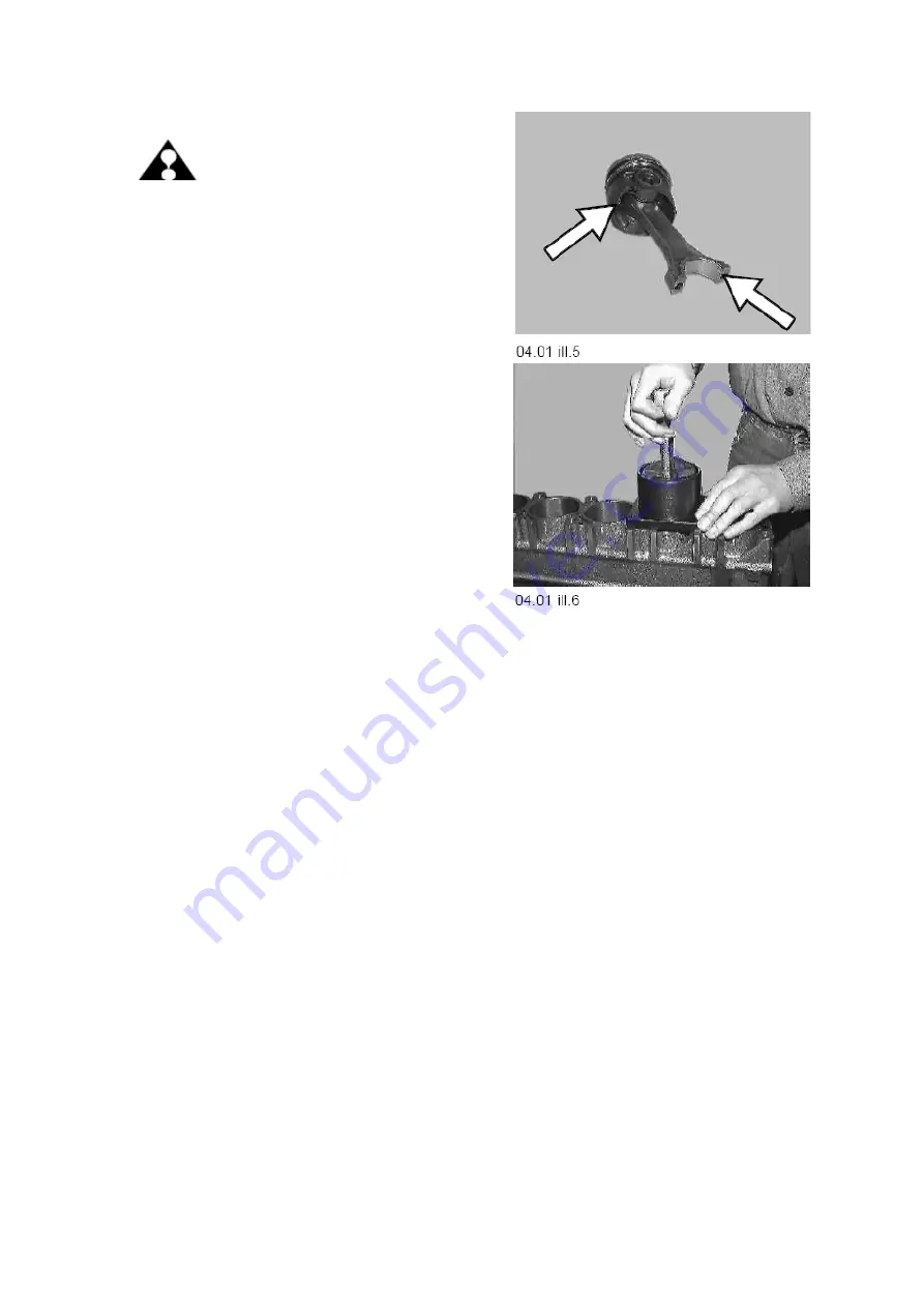
ATTENTION:
For assembly of piston and
connecting rod, take care that
positioning notch of
connecting rod bearing is
opposite to the clearance
recess for oil injection nozzle.
NOTE:
For best result position rings with
piston gap about one third of a turn a part
from each others gap.
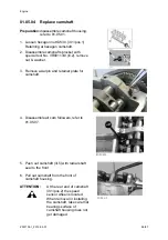
NOTE:
When inserting the piston into cylinder
bore, with special tool No. 2300714/1, take
care that arrow marking on piston top pointing
to the front.
Содержание Marine Engine 2012 Series
Страница 35: ...General 35 65 Z001138 1_2013 02 01 Trouble Indication ...
Страница 36: ...General Preliminary Service Manual MARINE 2012 Z001138 1_2013 02 01 36 65 ...
Страница 51: ...General 51 65 Z001138 1_2013 02 01 G Notes on safety ...
Страница 69: ...Engine Z001138 1_2013 02 01 4 87 Kapitel MOUNT BRACKET COVER T BELT GASKET SET ...
Страница 131: ...Engine Z001138 1_2013 02 01 66 87 12 Unscrew frame sealing from engine housing NOTE Do not puncture frame seal ...
Страница 154: ...Fuel System Z001138 1_2013 02 01 2 51 ...
Страница 159: ...Fuel System 7 51 Z001138 1_2013 02 01 03 00 03 Unit injector ...
Страница 190: ...Fuel System Z001138 1_2013 02 01 38 51 Schema Injection Timing Device ITD ...
Страница 211: ...Cooling System 5 21 Z001138 1_2013 02 01 ...
Страница 231: ...Electrical System Z001138 1_2013 02 01 4 47 ...
Страница 235: ...Electrical System Z001138 1_2013 02 01 8 47 ...
Страница 236: ...Electrical System 9 47 Z001138 1_2013 02 01 ...
Страница 238: ...Electrical System 11 47 Z001138 1_2013 02 01 ...
Страница 244: ...Electrical System 17 47 Z001138 1_2013 02 01 06 05 03 Wiring Diagram E Box Wiring Diagram 2181123 0 ...
Страница 245: ...Electrical System Z001138 1_2013 02 01 18 47 06 05 04 Wiring Diagram E Box Wiring Diagram 2181134 0 ...
Страница 246: ...Electrical System 19 47 Z001138 1_2013 02 01 06 05 05 Wiring Diagram External E Box Diagram 2181141 0 ...
Страница 262: ...Electrical System 35 47 Z001138 1_2013 02 01 06 10 Actor and Sensor 06 10 01 Component configuration engine ...


