


Electrical System
45/47
Z001138-1_2013-02-01
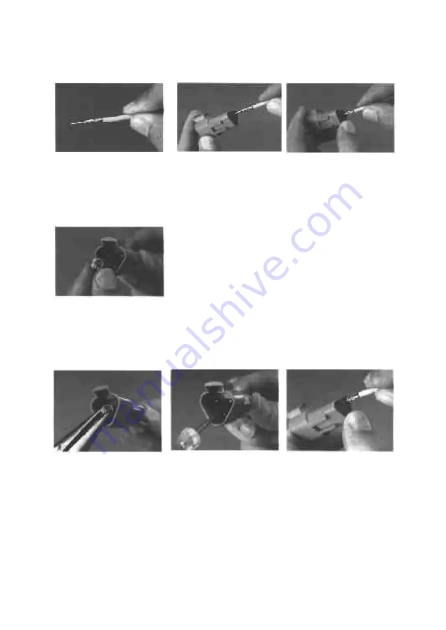
Contact insertion
Grasp contact approximately
(25,4mm) one inch behind
the contact crimp barrel.
Hold connector with rear
grommet facing you.
Push contact straight into
connector grommet until a
positive stop is felt. A
slight tug will confirm that
it is properly locked in
place.
Once all contacts are in place, insert orange wedge
with arrow pointing toward exterior locking
mechanism. The orange wedge will snap into place.
Rectangular wedges are not oriented. The may go in
either way.
NOTE:
The receptacle is shown - use the same
procedure for plug.
Contact removal
Remove orange wedge
using needle nose pliers or
a hook shaped wire to pull
wedge straight out.
To remove the contacts,
gently pull wire backwards,
while at the same time
releasing the locking finger
by moving it away from the
contact with a screwdriver.
Hold the rear seal in place,
as removing the contact
will displace the seal.
Содержание Marine Engine 2012 Series
Страница 35: ...General 35 65 Z001138 1_2013 02 01 Trouble Indication ...
Страница 36: ...General Preliminary Service Manual MARINE 2012 Z001138 1_2013 02 01 36 65 ...
Страница 51: ...General 51 65 Z001138 1_2013 02 01 G Notes on safety ...
Страница 69: ...Engine Z001138 1_2013 02 01 4 87 Kapitel MOUNT BRACKET COVER T BELT GASKET SET ...
Страница 131: ...Engine Z001138 1_2013 02 01 66 87 12 Unscrew frame sealing from engine housing NOTE Do not puncture frame seal ...
Страница 154: ...Fuel System Z001138 1_2013 02 01 2 51 ...
Страница 159: ...Fuel System 7 51 Z001138 1_2013 02 01 03 00 03 Unit injector ...
Страница 190: ...Fuel System Z001138 1_2013 02 01 38 51 Schema Injection Timing Device ITD ...
Страница 211: ...Cooling System 5 21 Z001138 1_2013 02 01 ...
Страница 231: ...Electrical System Z001138 1_2013 02 01 4 47 ...
Страница 235: ...Electrical System Z001138 1_2013 02 01 8 47 ...
Страница 236: ...Electrical System 9 47 Z001138 1_2013 02 01 ...
Страница 238: ...Electrical System 11 47 Z001138 1_2013 02 01 ...
Страница 244: ...Electrical System 17 47 Z001138 1_2013 02 01 06 05 03 Wiring Diagram E Box Wiring Diagram 2181123 0 ...
Страница 245: ...Electrical System Z001138 1_2013 02 01 18 47 06 05 04 Wiring Diagram E Box Wiring Diagram 2181134 0 ...
Страница 246: ...Electrical System 19 47 Z001138 1_2013 02 01 06 05 05 Wiring Diagram External E Box Diagram 2181141 0 ...
Страница 262: ...Electrical System 35 47 Z001138 1_2013 02 01 06 10 Actor and Sensor 06 10 01 Component configuration engine ...