Engine
13/87
Z001138-1_2013-02-01
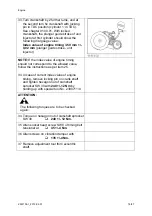
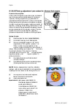
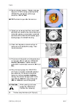
ATTENTION:
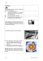
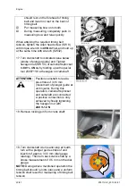
When putting on tension gauge No. VR00515/0,
consider the following:
The two stop trunnions
(ill.20/pos.2)should rest on the forehead
of timing belt and must not rest on the
back of timing belt
Put measuring bow onto tooth.
During measuring, completely push in
measuring bow and relax quickly.
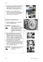
When attaining the required timing belt tension,
tighten the Allen head screw SW 8 with torque
wrench to
45
Nm +/-4,
and hold up at the same
time with wrench SW32.
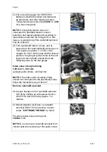
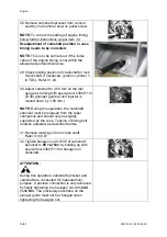
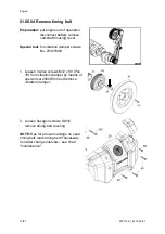
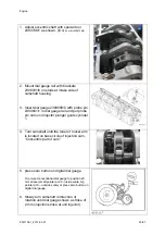
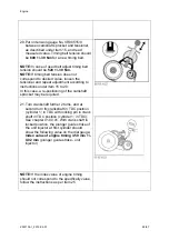
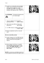
21. Remove locking pin from crank shaft.
22. Turn crankshaft 4 turns and stop at fourth
turn with a plunger guide stroke of unit
injector of approx. 3.30 mm (dial gauge
reading).
23. Then turn back crank shaft by a stroke
measurement of 0.5 mm on the dial gauge.
NOTE:
During above mentioned operation the
timing belt should run into place and a uniform
tension shall result for measuring of timing belt
tension.
6x
Содержание Marine Engine 2012 Series
Страница 35: ...General 35 65 Z001138 1_2013 02 01 Trouble Indication ...
Страница 36: ...General Preliminary Service Manual MARINE 2012 Z001138 1_2013 02 01 36 65 ...
Страница 51: ...General 51 65 Z001138 1_2013 02 01 G Notes on safety ...
Страница 69: ...Engine Z001138 1_2013 02 01 4 87 Kapitel MOUNT BRACKET COVER T BELT GASKET SET ...
Страница 131: ...Engine Z001138 1_2013 02 01 66 87 12 Unscrew frame sealing from engine housing NOTE Do not puncture frame seal ...
Страница 154: ...Fuel System Z001138 1_2013 02 01 2 51 ...
Страница 159: ...Fuel System 7 51 Z001138 1_2013 02 01 03 00 03 Unit injector ...
Страница 190: ...Fuel System Z001138 1_2013 02 01 38 51 Schema Injection Timing Device ITD ...
Страница 211: ...Cooling System 5 21 Z001138 1_2013 02 01 ...
Страница 231: ...Electrical System Z001138 1_2013 02 01 4 47 ...
Страница 235: ...Electrical System Z001138 1_2013 02 01 8 47 ...
Страница 236: ...Electrical System 9 47 Z001138 1_2013 02 01 ...
Страница 238: ...Electrical System 11 47 Z001138 1_2013 02 01 ...
Страница 244: ...Electrical System 17 47 Z001138 1_2013 02 01 06 05 03 Wiring Diagram E Box Wiring Diagram 2181123 0 ...
Страница 245: ...Electrical System Z001138 1_2013 02 01 18 47 06 05 04 Wiring Diagram E Box Wiring Diagram 2181134 0 ...
Страница 246: ...Electrical System 19 47 Z001138 1_2013 02 01 06 05 05 Wiring Diagram External E Box Diagram 2181141 0 ...
Страница 262: ...Electrical System 35 47 Z001138 1_2013 02 01 06 10 Actor and Sensor 06 10 01 Component configuration engine ...


