Engine
15/87
Z001138-1_2013-02-01
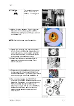
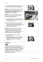
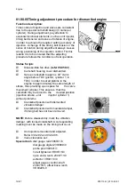
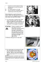
28. Remove camshaft sprocket from conical
seat by one hammer blow on puller screw.
NOTE:
To correct the setting of engine timing
follow further instructions as per item 30.
Readjustment of camshaft position in case
timing needs to be corrected.
NOTE:
This is to be carried out, if the index
value of the engine timing is not within the
allowed adjustment tolerance.
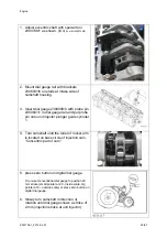
29. Check locking position of crankshaft or lock
crank shaft, if necessary. (piston; cylinder 1;
in TDC). Refer 01.00.
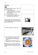
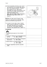
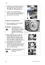
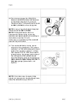
30. Adjust camshaft to 3,59 mm on the dial
gauge by turning with special tool 2300711/0
(ill.30).(plunger guide at unit injector is
moved down by 3,59 mm.)
NOTE:
During this operation, the camshaft
sprocket must be released from the taper
connection and should only be slightly
supported by the cone. Tension of timing belt
remains adjusted, as described before.
31. Remove locking pin from crank shaft.
Refer 01.00.01
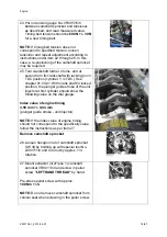
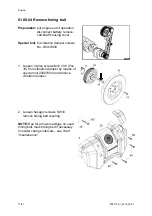
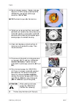
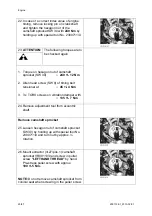
32. Tighten hexagon nut SW 30 of camshaft
sprocket to
80 +/-4 Nm
by holding up with
special tool 2300711/0 at hexagon on
camshaft.
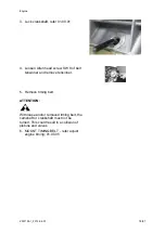
ATTENTION:
During this operation, camshaft sprocket and
camshaft are connected for measurement
purpose. A positive connection is only achieved
by finally tightening the hexagon nut with
240
+/-12 Nm.
The previously set stroke on the
plunger guide must not be changed when
tightening the hexagon nut.
Содержание Marine Engine 2012 Series
Страница 35: ...General 35 65 Z001138 1_2013 02 01 Trouble Indication ...
Страница 36: ...General Preliminary Service Manual MARINE 2012 Z001138 1_2013 02 01 36 65 ...
Страница 51: ...General 51 65 Z001138 1_2013 02 01 G Notes on safety ...
Страница 69: ...Engine Z001138 1_2013 02 01 4 87 Kapitel MOUNT BRACKET COVER T BELT GASKET SET ...
Страница 131: ...Engine Z001138 1_2013 02 01 66 87 12 Unscrew frame sealing from engine housing NOTE Do not puncture frame seal ...
Страница 154: ...Fuel System Z001138 1_2013 02 01 2 51 ...
Страница 159: ...Fuel System 7 51 Z001138 1_2013 02 01 03 00 03 Unit injector ...
Страница 190: ...Fuel System Z001138 1_2013 02 01 38 51 Schema Injection Timing Device ITD ...
Страница 211: ...Cooling System 5 21 Z001138 1_2013 02 01 ...
Страница 231: ...Electrical System Z001138 1_2013 02 01 4 47 ...
Страница 235: ...Electrical System Z001138 1_2013 02 01 8 47 ...
Страница 236: ...Electrical System 9 47 Z001138 1_2013 02 01 ...
Страница 238: ...Electrical System 11 47 Z001138 1_2013 02 01 ...
Страница 244: ...Electrical System 17 47 Z001138 1_2013 02 01 06 05 03 Wiring Diagram E Box Wiring Diagram 2181123 0 ...
Страница 245: ...Electrical System Z001138 1_2013 02 01 18 47 06 05 04 Wiring Diagram E Box Wiring Diagram 2181134 0 ...
Страница 246: ...Electrical System 19 47 Z001138 1_2013 02 01 06 05 05 Wiring Diagram External E Box Diagram 2181141 0 ...
Страница 262: ...Electrical System 35 47 Z001138 1_2013 02 01 06 10 Actor and Sensor 06 10 01 Component configuration engine ...


