Electrical System
Z001138-1_2013-02-01
34/47
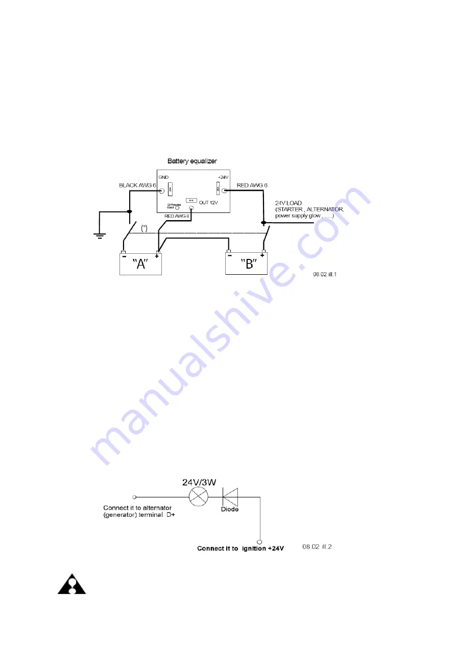
06.08.02 Voltage regulator 24V-12V equalizer 2179789-0 löschen
2176897-0 DC-DC converter 24/12
Power supply to equalizer recommended wire gauge size.
Starter must be connecting by customer use a wire min. AWG 0 (50 mm²)
connect a red wire AWG 8 (6 mm²) at battery "A" positive te12V
connect a red wire AWG 6 (10 mm²) at battery "B" positive te24V
connect a black wire AWG 6 (10 mm²) directly at battery "A" negative terminal.
* Note:
......Mainswitches are mechanically interlinked.
X21 ARMATUREN PLUG 6-POLE: --> USE ONLY 12 VOLT INSTRUMENTS
pin1
pin2
pin3
pin4
pin5
pin6
60810--> check engine lamp (12V/2W)
60616--> glow lamp (12V/2W)
60614--> temperature instruments (12V)
60613--> engine speed instruments (12V)
50000--> starter terminal 50 (detection of start)
15000--> ignition connect it to the ignition-switch of the marine (protect
with 5 Amp fuse)
Note:
The glow lamp has 2 functions --> at first it works as glow lamp after start
it works as oil pressure lamp.
ALTERNATOR
B+ must be connected by customer --> use a wire AWG 6 (10 mm²) charging
control --> must be connected by customer.
ATTENTION:
Please observer and follow Original enclosed manufactures
recommendation!
Содержание Marine Engine 2012 Series
Страница 35: ...General 35 65 Z001138 1_2013 02 01 Trouble Indication ...
Страница 36: ...General Preliminary Service Manual MARINE 2012 Z001138 1_2013 02 01 36 65 ...
Страница 51: ...General 51 65 Z001138 1_2013 02 01 G Notes on safety ...
Страница 69: ...Engine Z001138 1_2013 02 01 4 87 Kapitel MOUNT BRACKET COVER T BELT GASKET SET ...
Страница 131: ...Engine Z001138 1_2013 02 01 66 87 12 Unscrew frame sealing from engine housing NOTE Do not puncture frame seal ...
Страница 154: ...Fuel System Z001138 1_2013 02 01 2 51 ...
Страница 159: ...Fuel System 7 51 Z001138 1_2013 02 01 03 00 03 Unit injector ...
Страница 190: ...Fuel System Z001138 1_2013 02 01 38 51 Schema Injection Timing Device ITD ...
Страница 211: ...Cooling System 5 21 Z001138 1_2013 02 01 ...
Страница 231: ...Electrical System Z001138 1_2013 02 01 4 47 ...
Страница 235: ...Electrical System Z001138 1_2013 02 01 8 47 ...
Страница 236: ...Electrical System 9 47 Z001138 1_2013 02 01 ...
Страница 238: ...Electrical System 11 47 Z001138 1_2013 02 01 ...
Страница 244: ...Electrical System 17 47 Z001138 1_2013 02 01 06 05 03 Wiring Diagram E Box Wiring Diagram 2181123 0 ...
Страница 245: ...Electrical System Z001138 1_2013 02 01 18 47 06 05 04 Wiring Diagram E Box Wiring Diagram 2181134 0 ...
Страница 246: ...Electrical System 19 47 Z001138 1_2013 02 01 06 05 05 Wiring Diagram External E Box Diagram 2181141 0 ...
Страница 262: ...Electrical System 35 47 Z001138 1_2013 02 01 06 10 Actor and Sensor 06 10 01 Component configuration engine ...


