NOISE ATTENUATION
Page NOISE ATTENUATION-4
Z001007/0_4_September 2007
INSTALLATION INSTRUCTION
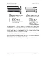
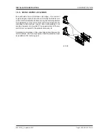
Before attaching the noise-absorbing material, make sure that there is sufficient space for movements of the
engine during operation. Noise-absorbing material is available in different types and thickness.
Provide a free space of 8" (180 mm) (ill. 14/4) in front of the engine, to permit its dismantling.
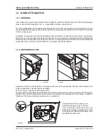
14. 3. NOISE ABSORBING HOODS AS SUPERSTRUCTURE
On small commodity boats and normally on all sport boats, at first engine and reversing gear are provided with
an elastic suspension - see chapter 3. However, in case of an elastic stem tube, no elastic coupling may be
mounted.
Then the engine compartment preferably is built as self-containted construction, with a hinged cover as top (ill.
14/3).
Attention:
Always consider enough space for maintenance of the engine - see respective operating instructions.
The engine protection is made of 1/12" (2 mm) steel plate or 3/4" (19 mm) plywood.
A 3/8" (10 mm) rubber strip is used as cover sealing.
For ventilation of the engine, two air intakes (see chapter 7) for sufficient air supply are to be provided. The air
intakes are connected to the bottom edge of the engine compartment by means of rubber hoses which ensures
sufficient noise reduction without any further measures.
Exhaust air of the engine compartment is conducted via two noise catchers with the some cross section as that
of the air intakes. These noise catchers must be insulated on both sides with the same material used for the inner
side of the engine protection.
In hot regions it may be necessary to install fans (see chapter 7.8) for air exhaust.
Atmospheric temperature of the engine may rise to a max. value of 40 - 45°C only. However, a temperature as
low as possible should be the aim.
ill. 14/4
Содержание 4 Cylinders
Страница 60: ...FUEL SYSTEM Page FUEL SYSTEM 2 Z001007 0_4_September 2007 INSTALLATION INSTRUCTION 7 FUEL SYSTEM NOTES ...
Страница 82: ...SAFETY COVERS Page SAFETY COVERS 2 Z001007 0_4_September 2007 INSTALLATION INSTRUCTION 11 SAFETY COVERS NOTES ...
Страница 86: ...BILGE PUMPS Page BILGE PUMPS 2 Z001007 0_4_September 2007 INSTALLATION INSTRUCTION 12 BILGE PUMPS NOTES ...
Страница 90: ...CABIN HEATING Page CABIN HEATING 2 Z001007 0_4_September 2007 INSTALLATION INSTRUCTION 13 CABIN HEATING NOTES ...
Страница 100: ...CONTROL STATION Page CONTROL STATION 2 Z001007 0_4_September 2007 INSTALLATION INSTRUCTION 15 CONTROL STATION NOTES ...
Страница 168: ...APPENDIX Page APPENDIX 2 Z001007 0_4_September 2007 INSTALLATION INSTRUCTION 18 APPENDIX NOTES ...
Страница 170: ...APPENDIX Page APPENDIX 4 Z001007 0_4_September 2007 INSTALLATION INSTRUCTION THIS PAGE IS INTENTIONALLY BLANK ...
Страница 172: ...APPENDIX Page APPENDIX 6 Z001007 0_4_September 2007 INSTALLATION INSTRUCTION THIS PAGE IS INTENTIONALLY BLANK ...
Страница 173: ...Z001007 0_4_September 2007 Page APPENDIX 7 APPENDIX INSTALLATION INSTRUCTION ...
Страница 174: ...APPENDIX Page APPENDIX 8 Z001007 0_4_September 2007 INSTALLATION INSTRUCTION THIS PAGE IS INTENTIONALLY BLANK ...

