


ENGINE INSTALLATION
Page ENGINE INSTALLATION-10
Z001007/0_4_September 2007
INSTALLATION INSTRUCTION
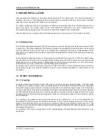
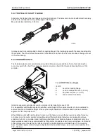
5. 10. ELASTIC SHAFT COUPLING
For engines with elastic suspension and a rigid stem bushing, an elastic shaft coupling is always to be mounted.
Even for a rigid engine suspension, an elastic propeller shaft coupling should be mounted if there is any risk that
the engine may change its position with regard to the propeller shaft, e.g. with different load of the boat.
Never use the elastic shaft coupling together with the elastically supported stem bushing. This may result in heavy
vibrations. Elastic engine suspension and elastically supported shaft bushing may, however, be used without
elastic coupling.
Engines provided for operation under heavy conditions, e.g. way through ice, are always to be equipped with
elastic propeller shaft coupling. A special thrust bearing for the propeller shaft is also to be mounted. The elastic
coupling should be situated between reversing gear and thrust bearing, to avoid tensions between the parts.
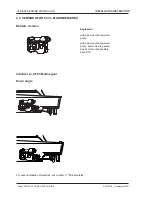
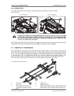
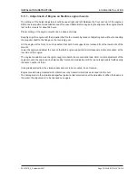
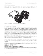
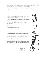
5.11. STEP BEARING
If the distance between the supports (a in ill. 12 and 13) exceeds 6 1/2 ft (2 m), a step bearing is to be mounted.
The correct distance between the step bearing and the engine is of utmost importance, which requires a
computation of vibrations.
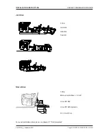
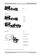
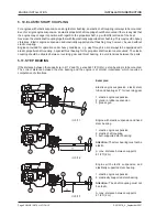
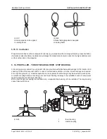
ill. 5/13
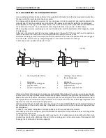
ill. 5/12
ill. 5/11
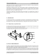
Engine with elastic suspension and
elastically supported stem bearing
1 elastic engine suspension
2 elastically supported stem bearing
Attention:
The shaft coupling must not
be elastic.
A max. distance between supports
6 1/2 ft (2 m)
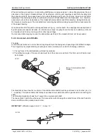
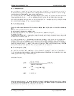
Elastic engine suspension, elastic stem
tube and bearing at 8° for reversing gear
1 elastic engine suspension
2 gland in rubber suspension
3 grease gun
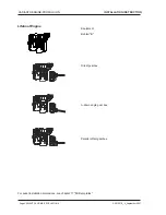
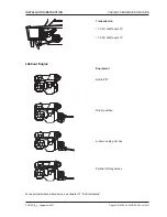
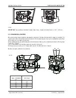
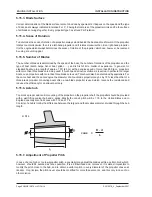
Engine with elastic suspension and fixed
stem bearing
1 elastic engine suspension
2 elastic shaft coupling
3 butt-supported stem bearing
Attention:
The stem bearing must not be
elastic.
A max. distance between supports
6 1/2 ft (2 m)
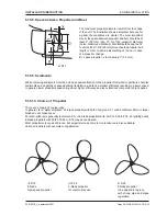
Examples:
Содержание 4 Cylinders
Страница 60: ...FUEL SYSTEM Page FUEL SYSTEM 2 Z001007 0_4_September 2007 INSTALLATION INSTRUCTION 7 FUEL SYSTEM NOTES ...
Страница 82: ...SAFETY COVERS Page SAFETY COVERS 2 Z001007 0_4_September 2007 INSTALLATION INSTRUCTION 11 SAFETY COVERS NOTES ...
Страница 86: ...BILGE PUMPS Page BILGE PUMPS 2 Z001007 0_4_September 2007 INSTALLATION INSTRUCTION 12 BILGE PUMPS NOTES ...
Страница 90: ...CABIN HEATING Page CABIN HEATING 2 Z001007 0_4_September 2007 INSTALLATION INSTRUCTION 13 CABIN HEATING NOTES ...
Страница 100: ...CONTROL STATION Page CONTROL STATION 2 Z001007 0_4_September 2007 INSTALLATION INSTRUCTION 15 CONTROL STATION NOTES ...
Страница 168: ...APPENDIX Page APPENDIX 2 Z001007 0_4_September 2007 INSTALLATION INSTRUCTION 18 APPENDIX NOTES ...
Страница 170: ...APPENDIX Page APPENDIX 4 Z001007 0_4_September 2007 INSTALLATION INSTRUCTION THIS PAGE IS INTENTIONALLY BLANK ...
Страница 172: ...APPENDIX Page APPENDIX 6 Z001007 0_4_September 2007 INSTALLATION INSTRUCTION THIS PAGE IS INTENTIONALLY BLANK ...
Страница 173: ...Z001007 0_4_September 2007 Page APPENDIX 7 APPENDIX INSTALLATION INSTRUCTION ...
Страница 174: ...APPENDIX Page APPENDIX 8 Z001007 0_4_September 2007 INSTALLATION INSTRUCTION THIS PAGE IS INTENTIONALLY BLANK ...


