


Z001007/0_4_September 2007
Page COOLING SYSTEM-5
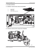
COOLING SYSTEM
INSTALLATION INSTRUCTION
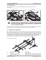
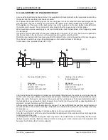
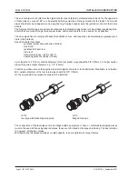
Apply a proper sealing agent, e.g. Permatex, on the screw passages. Sheet boats should have a screwed pipe
joint welded to the ship bottom, on which the bottom valve is fastened with screws. On the bottom side, a screen
is to be fixed. Apply a proper sealing agent between valve and screwing thread.
When fixing the floor valve, there should be sufficient free space around the valve to permit an easy opening and
closing of the valve. If this space is too small, an intermediate piece can be fixed below the valve. In many cases
a remote control will be required.
ill. 6/4
ill. 6/5
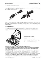
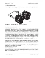
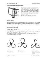
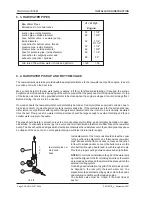
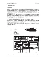
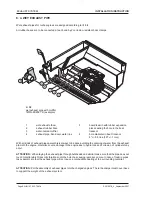
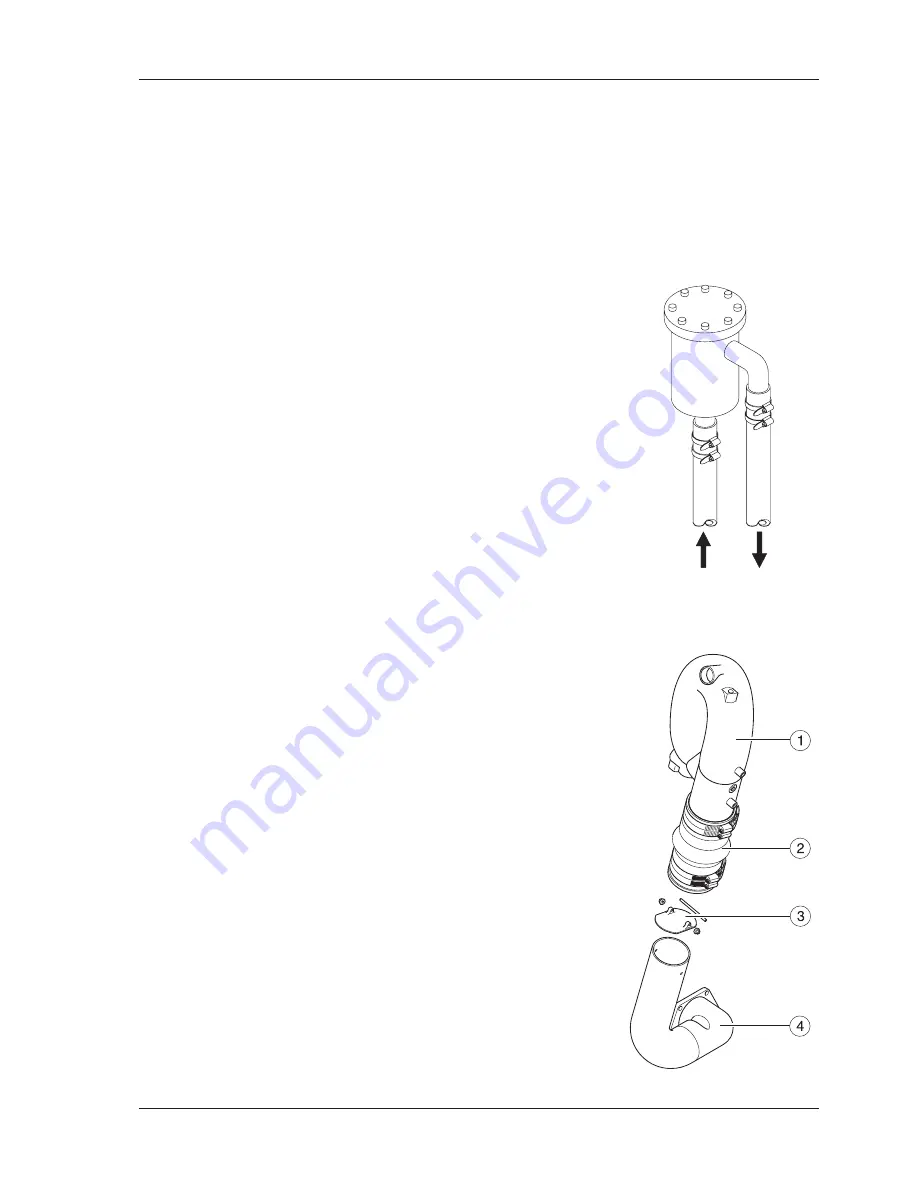
6. 6. COOLING WATER PIPES / EXHAUST CONNECTION
All STEYR MOTORS MARINE Diesels are equipped with a water cooled
exhaust gas elbow, as shown on ill. 6/5 . At the exhaust gas muzzle the raw
water is injected into the tail pipe for cooling of the exhaust gases.
When designing the exhaust elbow particular importance was attached to a
relatively high exhaust duct in order to avoid the entering of back wash. In the
adjoining exhaust pipe a splash flap is to be installed in addition.
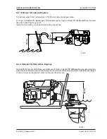
In case of insufficient difference in level between exhaust gas outlet and sea
water surface (boad loaded) a high riser exhaust elbow (optional) is to be
installed.
See section 8 Exhaust System.
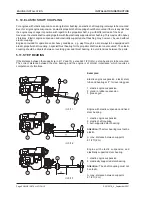
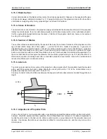
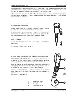
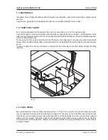
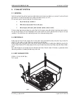
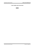
6. 5. RAW WATER FILTER
During coasting trade, on the pier etc., it cannot be avoided that small
particles of mud, sand and other dirt enter into the water inlet.
A filter in the suction pipe must be fitted so that these contaminations can be
separated. A raw water filter also helps to increase the pump life, thus
preventing engine defects due to insufficient cooling water supply.
Ill. 6/4 shows one of the Sherewood filters which may be installed with easy
acces in a bulkhead.
In case of severe contaminations it may be necessary to install a filter of
special size.
The minimum flow of the filter is 140 l/min.
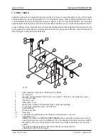
1
exhaust gas elbow
2
connecting piece
3
splash flap
4
tail pipe with flange
Содержание 4 Cylinders
Страница 60: ...FUEL SYSTEM Page FUEL SYSTEM 2 Z001007 0_4_September 2007 INSTALLATION INSTRUCTION 7 FUEL SYSTEM NOTES ...
Страница 82: ...SAFETY COVERS Page SAFETY COVERS 2 Z001007 0_4_September 2007 INSTALLATION INSTRUCTION 11 SAFETY COVERS NOTES ...
Страница 86: ...BILGE PUMPS Page BILGE PUMPS 2 Z001007 0_4_September 2007 INSTALLATION INSTRUCTION 12 BILGE PUMPS NOTES ...
Страница 90: ...CABIN HEATING Page CABIN HEATING 2 Z001007 0_4_September 2007 INSTALLATION INSTRUCTION 13 CABIN HEATING NOTES ...
Страница 100: ...CONTROL STATION Page CONTROL STATION 2 Z001007 0_4_September 2007 INSTALLATION INSTRUCTION 15 CONTROL STATION NOTES ...
Страница 168: ...APPENDIX Page APPENDIX 2 Z001007 0_4_September 2007 INSTALLATION INSTRUCTION 18 APPENDIX NOTES ...
Страница 170: ...APPENDIX Page APPENDIX 4 Z001007 0_4_September 2007 INSTALLATION INSTRUCTION THIS PAGE IS INTENTIONALLY BLANK ...
Страница 172: ...APPENDIX Page APPENDIX 6 Z001007 0_4_September 2007 INSTALLATION INSTRUCTION THIS PAGE IS INTENTIONALLY BLANK ...
Страница 173: ...Z001007 0_4_September 2007 Page APPENDIX 7 APPENDIX INSTALLATION INSTRUCTION ...
Страница 174: ...APPENDIX Page APPENDIX 8 Z001007 0_4_September 2007 INSTALLATION INSTRUCTION THIS PAGE IS INTENTIONALLY BLANK ...


