


ENGINE INSTALLATION
Page ENGINE INSTALLATION-12
Z001007/0_4_September 2007
INSTALLATION INSTRUCTION
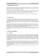
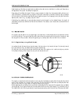
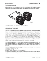
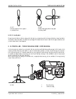
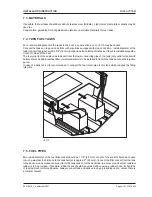
5.13. TWIN INSTALLATION
When mounting engines with one propeller each, choose the reversing gears in such a way that the starboard
propeller rotates clockwise and the port side propeller counterclockwise, seen in the direction of the bow.
centre distance of shafts A (min. dimension) approx.: > 31" (> 787 mm)
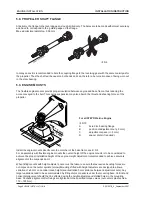
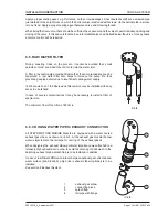
5. 14. SHAFT AND STEM TUBE
To choose the right components of engine, reversing gear and propeller with regard to the respective ratio of load,
follow the recommendations as to power and speed of various engines, to be found in the product information
"marine engines". The combination of reduction of speed, shaft diameter and propeller size may be computed
based on our recommendations on propellers, included in a separate pamphlet. Computation and determination
of the propeller size may also be done by STEYR Motorentechnik (claim in time, together with drawing). Consider
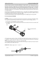
a sufficient distance between propeller, hull, keel, stem tube and oar. To permit a dismantling of the reversing
gear or the coupling, a sternward displacement of the propeller shaft for at least 8" (200 mm) should be possible.
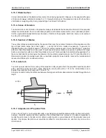
Also take care that no transept bulkheads do interfire with dismantling. Between propeller and stem bearing a
min. distance of 1" (25 mm) is to be kept in order to prevent the propeller from bucking against the stem bearing.
Before mounting the shaft, its straightness is to be controlled. Check by means of a dial gauge that the shaft
flanges do not twist. Max. admissible axial fault 0,1 mm.
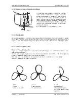
Before launching the boat, make sure that a propeller with correct pitch and diameter has been mounted. Also
check that the propeller shows the correct thread (R or L) for the provided sense of rotation.
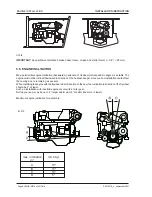
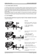
The exact alignment of the whole drive unit on the foundation is a condition for troublefree operation. On principle,
assembly and alignment is done in the order driving shaft - engine. Flange connections and couplings (even
elastic ones) must be released when aligning the parts connected. For elastic couplings follow the manufacturer's
instructions.
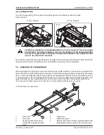
For alignment of the parts to be mounted a dial gauge with suitable holder and eventually a thickness gauge will
be necessary. Alignment always requires two checks:
vanishing check (contact accuracy) and
angularity check (no bends).
With two dial gauges, both checks can be done simultaneously.
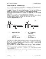
For each check, the part at which the dial gauge is fixed is to be moved for at least one turn. An exact alignment
of the part to be mounted mostly requires several checks. Because of that it is advisable to fix the dial gauge on
that part which can be turned more easily.
ill. 5/15
Содержание 4 Cylinders
Страница 60: ...FUEL SYSTEM Page FUEL SYSTEM 2 Z001007 0_4_September 2007 INSTALLATION INSTRUCTION 7 FUEL SYSTEM NOTES ...
Страница 82: ...SAFETY COVERS Page SAFETY COVERS 2 Z001007 0_4_September 2007 INSTALLATION INSTRUCTION 11 SAFETY COVERS NOTES ...
Страница 86: ...BILGE PUMPS Page BILGE PUMPS 2 Z001007 0_4_September 2007 INSTALLATION INSTRUCTION 12 BILGE PUMPS NOTES ...
Страница 90: ...CABIN HEATING Page CABIN HEATING 2 Z001007 0_4_September 2007 INSTALLATION INSTRUCTION 13 CABIN HEATING NOTES ...
Страница 100: ...CONTROL STATION Page CONTROL STATION 2 Z001007 0_4_September 2007 INSTALLATION INSTRUCTION 15 CONTROL STATION NOTES ...
Страница 168: ...APPENDIX Page APPENDIX 2 Z001007 0_4_September 2007 INSTALLATION INSTRUCTION 18 APPENDIX NOTES ...
Страница 170: ...APPENDIX Page APPENDIX 4 Z001007 0_4_September 2007 INSTALLATION INSTRUCTION THIS PAGE IS INTENTIONALLY BLANK ...
Страница 172: ...APPENDIX Page APPENDIX 6 Z001007 0_4_September 2007 INSTALLATION INSTRUCTION THIS PAGE IS INTENTIONALLY BLANK ...
Страница 173: ...Z001007 0_4_September 2007 Page APPENDIX 7 APPENDIX INSTALLATION INSTRUCTION ...
Страница 174: ...APPENDIX Page APPENDIX 8 Z001007 0_4_September 2007 INSTALLATION INSTRUCTION THIS PAGE IS INTENTIONALLY BLANK ...


