Z001007/0_4_September 2007
Page NOISE ATTENUATION-3
NOISE ATTENUATION
INSTALLATION INSTRUCTION
14. NOISE ATTENUATION
14. 1. GENERAL
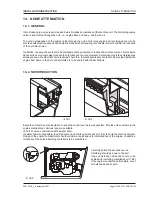
In most cases a low noise level is required, which implies an insulation of the machine unit. The disturbing engine
noise is transmitted through the hull - i.e. engine base and body - and by the air.
To avoid a propagation of the engine noise through the hull, as first step engine and reversing gear are to be
provided with elastic suspensions and elastic propeller shaft coupling (see chapter 3) which results in a reduction
of the hull-latent noise.
In addition, the acoustic source is to be shielded as far as possible, to reduce the air-latent noise. This measure
above all is a very simple way to reduce the high-frequency noise. However, a small opening in the shielding may
already cause a considerable noise leakage. Therefore, insulating material should also be provided below the
engine bed, down to the hull, and all inlets are to be sealed with rubber bellows.
14. 2. NOISE REDUCTION
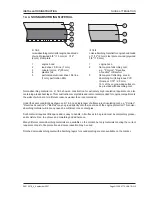
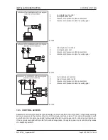
Equip the unit with a noise insulation to keep the sound level as low as possible. Provide noise catchers in the
engine compartment. Various type are available.
Ill. 14/1 shows a construction with a water drain.
If a water drain is not possible, the air tubes may be bent like a swanneck (ill. 14/2), to avoid the entering of water.
Design of the engine compartment should consider enough space for maintenance of the engine. In addition,
thickness of the noise-absorbing material is to be considered.
ill. 14/2
ill. 14/1
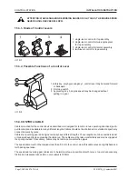
Carefully shield the acoustic source.
Shielding should go down to the hull.
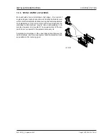
Gaps on hatches and bench covers to be
sealed with insulating material (see ill. 14/3)
If the engine is under the bottom plate, cover
all bulkheads and sheets.
ill. 14/3
Содержание 4 Cylinders
Страница 60: ...FUEL SYSTEM Page FUEL SYSTEM 2 Z001007 0_4_September 2007 INSTALLATION INSTRUCTION 7 FUEL SYSTEM NOTES ...
Страница 82: ...SAFETY COVERS Page SAFETY COVERS 2 Z001007 0_4_September 2007 INSTALLATION INSTRUCTION 11 SAFETY COVERS NOTES ...
Страница 86: ...BILGE PUMPS Page BILGE PUMPS 2 Z001007 0_4_September 2007 INSTALLATION INSTRUCTION 12 BILGE PUMPS NOTES ...
Страница 90: ...CABIN HEATING Page CABIN HEATING 2 Z001007 0_4_September 2007 INSTALLATION INSTRUCTION 13 CABIN HEATING NOTES ...
Страница 100: ...CONTROL STATION Page CONTROL STATION 2 Z001007 0_4_September 2007 INSTALLATION INSTRUCTION 15 CONTROL STATION NOTES ...
Страница 168: ...APPENDIX Page APPENDIX 2 Z001007 0_4_September 2007 INSTALLATION INSTRUCTION 18 APPENDIX NOTES ...
Страница 170: ...APPENDIX Page APPENDIX 4 Z001007 0_4_September 2007 INSTALLATION INSTRUCTION THIS PAGE IS INTENTIONALLY BLANK ...
Страница 172: ...APPENDIX Page APPENDIX 6 Z001007 0_4_September 2007 INSTALLATION INSTRUCTION THIS PAGE IS INTENTIONALLY BLANK ...
Страница 173: ...Z001007 0_4_September 2007 Page APPENDIX 7 APPENDIX INSTALLATION INSTRUCTION ...
Страница 174: ...APPENDIX Page APPENDIX 8 Z001007 0_4_September 2007 INSTALLATION INSTRUCTION THIS PAGE IS INTENTIONALLY BLANK ...

