


Z001007/0_4_September 2007
Page ENGINE INSTALLATION-11
ENGINE INSTALLATION
INSTALLATION INSTRUCTION
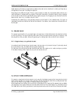
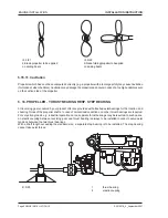
5.12. ADJUSTMENT OF ENGINE DRIVE UNIT
As soon as the base frame has been finished, the propeller shaft mounted and the other preparation works done,
the engine and the reversing gear can be mounted.
For engines with double reversing gears, the reversing gear is to be mounted first and exactly aligned to the
propeller shaft. Then the couplings are mounted, and the engines are aligned towards the reversing gear.
First adjustment of the engine on the boat can be done either on land or on the seas. Before final adjustment,
the boat should, however, be on the seas for some days so that the body can take its final shape.
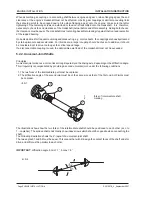
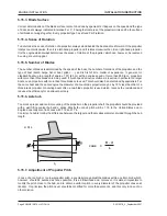
When mounting a marine reversing gear, it is recommended to check the parallelism of the flanges by means
of a dial gauge.
In this case, the propeller shaft is to be moved sternwards for approx. 3/8" (10 mm) and be well supported so
that the clearance in the stem tube is uniformly distributed (exactly center the shaft).
Rotate the reversing gear shaft and measure at first the radial off-size. Correct the position of the reversing gear.
Then check the axial off-size by a hinge dial gauge on the contact surfaces of the flange.
In both cases, max. possible off-size is 0,1mm.
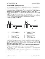
After having finished the adjustment, prepare supporting disks fitting between the engine-reversing gear bearers
and the rests on the engine. Measure the distances and prepare steel disks to be ground to the dimensions found.
Make all bores for the bearers, and screw on the engine and the reversing gear. Take care that all setscrews for
the high position are unscrewed so that the bearers do not rest on the screws but on the supporting disks. After
alignment, remove the setscrews for high position.
After launching the boat, check the adjustment once again. The boat with filled tanks and the required equipment
should have been on the seas for some days. Ship bodies are elastic and do not have the same shape when they
are propped up.
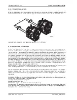
In case of a necessary readjustment, distance plates can be mounted under the bearers.
After start-up of the boat, verify at regular intervals that the adjustment of the machine unit has not changed due
to deformations of the body.
A bad alignment of engine and propeller shaft may cause a lot of disturbances and operating troubles. Such
troubles may also result in vibrations in the hull, in the reversing gear, and in a quick wear of the propeller shaft
bearings, the shaft and the stem tube supports
.
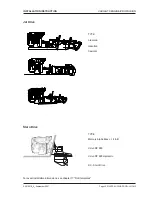
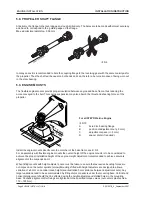
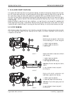
ill. 5/14
A
checking of radial off-size
1
dial gauge
2
flange on reversing gear
3
propeller shaft
4
support of propeller shaft
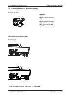
A
checking of axial off-size
(hinge dial gauge)
1
dial gauge
2
flange on reversing gear
3
propeller shaft
4
support of propeller shaft
Содержание 4 Cylinders
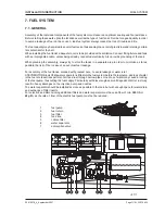
Страница 60: ...FUEL SYSTEM Page FUEL SYSTEM 2 Z001007 0_4_September 2007 INSTALLATION INSTRUCTION 7 FUEL SYSTEM NOTES ...
Страница 82: ...SAFETY COVERS Page SAFETY COVERS 2 Z001007 0_4_September 2007 INSTALLATION INSTRUCTION 11 SAFETY COVERS NOTES ...
Страница 86: ...BILGE PUMPS Page BILGE PUMPS 2 Z001007 0_4_September 2007 INSTALLATION INSTRUCTION 12 BILGE PUMPS NOTES ...
Страница 90: ...CABIN HEATING Page CABIN HEATING 2 Z001007 0_4_September 2007 INSTALLATION INSTRUCTION 13 CABIN HEATING NOTES ...
Страница 100: ...CONTROL STATION Page CONTROL STATION 2 Z001007 0_4_September 2007 INSTALLATION INSTRUCTION 15 CONTROL STATION NOTES ...
Страница 168: ...APPENDIX Page APPENDIX 2 Z001007 0_4_September 2007 INSTALLATION INSTRUCTION 18 APPENDIX NOTES ...
Страница 170: ...APPENDIX Page APPENDIX 4 Z001007 0_4_September 2007 INSTALLATION INSTRUCTION THIS PAGE IS INTENTIONALLY BLANK ...
Страница 172: ...APPENDIX Page APPENDIX 6 Z001007 0_4_September 2007 INSTALLATION INSTRUCTION THIS PAGE IS INTENTIONALLY BLANK ...
Страница 173: ...Z001007 0_4_September 2007 Page APPENDIX 7 APPENDIX INSTALLATION INSTRUCTION ...
Страница 174: ...APPENDIX Page APPENDIX 8 Z001007 0_4_September 2007 INSTALLATION INSTRUCTION THIS PAGE IS INTENTIONALLY BLANK ...


