background image

35

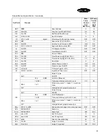
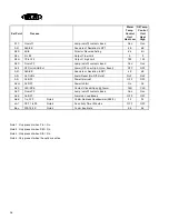
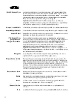
Secure Menu (Up and Enter - 5 seconds)

Set Point

Process

Water 

Temp. 

Control 

Unit

Heat Low

Oil Temp. 

Control 

Unit

Heat 
High

SEC

####

Security Code

4

4

FnC

HL/HH/L

Function (Lo/Hi heat Chiller)

HL

HL

Sto

0 to 100

Self Tune Offset Percent

0

0

InC

-500 to +500

Input Correction

0

0

Fil

OFF, 1 to 99

digital

Filter value 0=off (electrical noise)

OFF

OFF

SP2

###

Second Set Pt (COOLING)

0

0

Pd2

On/OFF

Link the I and D terms to PB2

ON

ON

Art

OFF, 1 to 99.99

Approach Rate outside PB1

OFF

OFF

tci

On/OFF

T/C Monitor On/OFF

OFF

OFF

FLO

On/OFF

Flow Monitor On/OFF

OFF

OFF

FCY

###

Flow in FREQ.

FSL

0 to 100

Flow Scale Low @ 25 Hz (CAL.)

6

6

FSH

0 to 255

Flow Scale High @ 225 Hz (CAL)

30

30

FLF

0 to 100

Flow Filter

2

2

SAF

On/OFF

Safety Thermo On/OFF

ON

ON

PrS

On/OFF

Pressure Input On/OFF

ON

ON

InP

J-/CA-/E-

T/C Input Type (J, K, E)

J

J

Int

OFF,0.1 to 540.0

Input Fault Timer (min.)

OFF

OFF

Ot1

Output 1 type

OnF

On/OFF

S1d

####

On/OFF differential

1 to 80t

Time proportioning cycle rate in sec.

20

20

#PuL

1 to 7

Pulse curve value 1 = linear, 7 = most non-
linear

PrP

Voltage/Current proportional output

Ot2

Output 2 type

OnF

ON/Off

S2d

####

On/Off differential

1 to 80

Time proportioning cycle rate in sec.

15

15

#PuL

1 to 7

Pulse curve value 1 = linear, 7 = most non-
linear

PrP

Voltage/Current proportional output

SEn

OFF<1 to 4000

Sensor rate of change (cnts or deg. per sec)

OFF

OFF

SCL

DEFAULTED

Scale low

0

0

SCH

DEFAULTED

Scale high

250

550

SPL

min - SCL

Set Pt. low limit

0

0

SPH

max- SCH

Set Pt. high limit

250

550

S1S

dir/rE

Direct or Reverse Acting

rE

rE

S1L

0 to 90

Output 1 low limit

0

0

S1H

10 to 102

Output 1 high limit

100

100

Содержание M2B

Страница 1: ... Rev A ...

Страница 2: ... custom configurations Air and water cooled chillers available in portable and central styles Cooling tower systems with full engineering capabilities Granulators shredders and size reduction systems Available with vacuum take away and special hopper configurations Robotics sprue pickers and downstream automation Custom end of arm tooling Quality OEM remanufacturing and updating of Sterlco water a...

Страница 3: ...nded to provide a complete overview of the unit and to give you step by step guidelines for the safe operation care and service of your unit We recommend that you thoroughly read this manual before initial start up These standard units may have many variations of optional features added to them relative to the customer s application or specific desires The illustrations used are to help you identi...

Страница 4: ...mp Soak 14 Sample Ramp Soak Program 17 Starting Ramp Soak 19 Options 20 Remote Set Point 20 Retransmission of Process Variable 21 Second Set Point Input 21 Flow Meter 21 Remote Thermocouple Monitor 21 Communications 21 SPI Protocol 24 Diagnostic Error Messages 26 Fault Reset Procedure 26 High Temperature Oil Reconfiguration 27 Field Calibration 28 Audit Temperature Inputs 28 Electrical Specificati...

Страница 5: ...ing 4 Have your unit s model number and serial number available when you call Sterling Return Goods Authorization RGA In order to better serve our customer s needs we ask that before returning material or equipment of any kind for any reason that you call Sterling at 1 800 783 7835 for a return goods authorization number RGA This is a mandatory policy to help us identify returned goods the reason ...

Страница 6: ... This manual shows the digital text as all caps however the actual readouts are a combination of caps and lower case letters CAUTION A warning intended to prevent physical harm to the operator or equipment Note Information to add clarity to the text The following illustration provides a reference for the side bar illustrations S P is used to denote what is currently visable in the SETPOINT display...

Страница 7: ...tics to check hardware functions Diagnostic lights are provided for the following functions low fluid pressure safety thermo high low alarms delivery and return probes and motor fail The M2B is panel mounted and has a membrane keypad with tactile feed back When properly installed with a sealing gasket the M2B is safe for water washdown Figure 1 P7 P8 H A2 T C D E Soldered Ribbon Cable K PUMP HIGH ...

Страница 8: ... now be adjusted for your installation Press SETPOINT Use ARROW to adjust Model Identification To determine the options that are included with the M2B use the following configurator The character X represents an option that is included ON 3 sec S P S P S P 3 sec 1 to 5 min S P RUN Options 0 STD 1 RS485 SPI 2 RS485 GEN 3 4 20 Heat Out 4 4 20 Cool Out 5 4 20 Heat Cool 6 RS232 GEN 7 Process Input 4 2...

Страница 9: ...ur system can be protected by installing a Line Filter Where external contactors or solenoids are used with relay output instruments an R C Snubber Network should be used The snubber installs easily directly across the field coil terminals of the relay or solenoid Do not run thermocouples RTD s or other class 2 wiring in the same conduit or area as power leads Maintain separation between wiring of...

Страница 10: ... operation HI HEAT Fluid heaters are on Hi to rapidly raise the fluid temperature LO HEAT Fluid heaters are at 50 COOL Fluid temperature is above setpoint and is being cooled Menu Security Level Status Displayed Value When Viewed Password Value To Enter Home Secondary Secure Locked Locked Locked 1 110 Home Secondary Secure Unlocked Locked Locked 2 101 Home Secondary Secure Unlocked Unlocked Locked...

Страница 11: ...te in the secondary menu Alarms reset automatically PROBE FAIL A temperature sensing probe has failed A delivery probe fail will display in the display Failure of the return probe will display The alarm will reset when the probe is replaced MOTOR FAIL Improper pump rotation motor out of phase or thermal overload This is a fatal fault which requires the main power to be disconnected to reset the M2...

Страница 12: ...re information Tune Fuzzy Logic Auxiliary set point Thermocouple Monitor Flow Alarms Autovent on Off and Duration 1 to 5 min High Low Heat Select Ramp Soak Run Hold Segment Time Remaining UP and DOWN ARROWs Depressing the UP and DOWN arrows simultaneously activates an optional output normally used for purge options UP and ENTER Depressing the UP and ENTER keys simultaneously will access the second...

Страница 13: ...actory default for the M2B is automatic half full heat If an autotune cycle is completed do not switch to low heat without performing a new autotune cycle Failure to autotune will result in poor control of the process Subsequent changes from one heat setting to another require autotune to be run Initiate Autotuning The controller will evaluate the process and select the P I D and Fuzzy Logic value...

Страница 14: ...tpoint to the desired value 4 While monitoring the process temperature or recording device decrease the proportional value by repeatedly halving the value until a small sustained temperature oscillation is observed Measure the period of one cycle of oscillation T 5 Divide the period of oscillation T by eight the resulting number is the correct rate time in seconds Multiply this number by four This...

Страница 15: ... way to program a ramp Instead of requiring the operator to calculate an approach rate the M2B does the calculation automatically The operator needs to program the target set point and the time desired to reach that set point When the ramp segment is executed by the controller it calculates the ramp required to reach the process temperature from starting set point to the programmed set point in th...

Страница 16: ...o change to if it is on Press ENTER Press INDEX once should appear Use the ARROW keys to change to if it is off Press ENTER Press INDEX should appear Skip this parameter for now and press INDEX once more will appear Use the ARROW keys to select time base seconds or minutes Press ENTER Press the INDEX key until appears From this point pressing INDEX will display the following items in the following...

Страница 17: ...ll be active for the period of and Set the segment times segment set points event alarms if they exist For the segments that are not used set the segment times to 0 and segment set points to the same value as the last active set point Event alarms may be set as necessary END is the last menu item for the Ramp Soak function END determines what the controller does when the program has ended To set t...

Страница 18: ...0 2TI 2nd Event 2 2SP 150 3TI 3rd Event 2 3SP 150 4TI 4th Event 2 4SP 100 5TI 5th Event 1 5SP 100 6TI 6th Event 2 6SP 50 7TI Un Used 0 7SP Hold Last Setpoint 50 Un Used GTI Un Used 0 GSP 50 END Stay at present set pt gSP HLd END Turn off outputs at end of program Oof END Repeat program at 1TI Lop ...

Страница 19: ...s now ready to run See Starting Ramp Soak S S S S S S S S S S S S P P P P P P P P P P P P S S S S S S S S S S S S P P P P P P P P P P P P Set the remaining points 8 9 and A G to zero S S S S S S S P P P P P P P or or Enter the secondary menu Follow the Ramp Soak setup steps to reach ...

Страница 20: ... The primary menu will change depending on the setting of menu item in the secondary menu If is off there is no change If is set to on the primary menu has three additional information items added after appears displays remaining time in the current segment displays total time of active segment displays the segment set point To exit primary menu press SET POINT key S P S P No Change S P Return to ...

Страница 21: ...enabled Press ENTER to change status Press INDEX twice Display Press the UP arrow to display Press ENTER Operation The M2B is capable of an analog remote set point input The operator can toggle the set point from local to remote input via the following sequence Depress the UP and ENTER keys simultaneously Depress the INDEX key to scroll through the menu until appears in the left display Depress th...

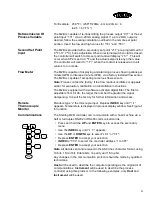
Страница 22: ...installation instructions The M2B is equipped with a software activated digital filter The filter is adjustable from 0 100 the larger the number the greater the signal dampening Consult the factory for further information and access Remote Thermocouple Monitor Monitors type J thermocouple input Depress INDEX key until appears Temperature is displayed in process display window See Figure 1 for loca...

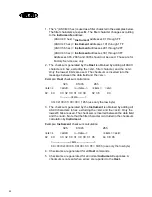
Страница 23: ...into the message between the data field and the etx Example Host checksum calculation 32h 0100h 26h stx L addr data cksm etx 02 4C 33 32 30 31 30 30 32 36 03 cksm 33 32 30 31 30 30 126h use only the low byte 3 The checksum generated by the Instrument is obtained by adding all ASCII characters in hex excluding the stx and the ack Only the lowest 8 bits are used The checksum is inserted between the ...

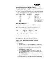
Страница 24: ...ument at address 32 Instrument responds to Host s last command with Error message stx L addr N error code ack 32h N 02h 02 4C 33 32 4E 30 32 06 Note the absence of Checksum N ASCII character 4Eh used to denote Error Present Table Of Error Messages Possible From Instrument error code 00 Not used 01 Undefined command Command not within acceptable range 02 Check sum error on received data from Host 0...

Страница 25: ...ormat 21H Echo Select Controller integrity command Supplies 4 bytes of ASCII in an open format that is to be returned when an Echo Poll command is received 22H Version poll Returns a version number AABB 0101 as 4 bytes of ASCII in an open format where AA SPI assigned version level BB Vendor assigned version level 30H Set point poll Returns the current process set point value in numeric format 31H ...

Страница 26: ...atus machine 2 poll Returns the status of the machine as 16 flag bits in open format The following bits are supported The rest are set to 0 Bit 0 Processing Bit 1 Alarm System Bit 2 Alarm Process Bit 3 Alarm Machine Bit 4 Fault Sensor Delivery Bit 5 Fault Sensor Return 48H Mode Machine Poll Returns the current status of temperature control unit if the machine is On 1 or Off 0 49H Mode Machine Sele...

Страница 27: ...press the INDEX and ENTER keypads together Index until and appears in the display Press the DOWN and ENTER keypads simultaneously to accept the factory default Both displays will flash then indicating re boot is complete The controller will automatically return to the run mode DISPLAY DESCRIPTION ACTION REQUIRED Flashing Ambient temperature out of range Reduce ambient temperature at controller con...

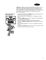
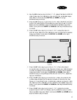
Страница 28: ...configuration Depress and hold the UP and ENTER keypads simultaneously for five 5 seconds to enter the secure menu will appear in the left display and will appear in the right display Depress the INDEX keypad until appears in the left display and appears in the right display Depress the UP arrow until appears in the right display Depress the DOWN and ENTER keypads simultaneously to enter the param...

Страница 29: ...t Temperature Indicator with an accuracy of 0 05 or better 4 Assortment of test leads Procedure 1 Power up Instrument and allow the M2B to warm up for 1 hour 2 Hold the ENTER and UP Arrow keys for 5 seconds The Menu will enter the SECURE MENU The displays will read and If not set the right display to and press ENTER The right display should blink and return to Press the INDEX key until you see and...

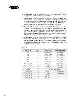
Страница 30: ... to go to CAL 4 Place the millivolt connection into connector C see Figure 4 Adjust your millivolt signal to 4 663 mV Make sure the calibration value is within the acceptable range see Table 1 and press the ENTER and DOWN arrow keys simultaneously to accept Repeat this step for Cal 5 0 0 0 0 adjust the input for 73 953mV 8 Press the UP arrow key to go to Cal 6 1 1 1 1 Place the wires for the remot...

Страница 31: ...value is within the acceptable range see Table 1 and press the ENTER and DOWN arrow keys simultaneously to accept 13 Press the UP arrow key to go to CAL B Now adjust the input to 200 Hz 131 5 Hz for 75 GPM Make sure the calibration value is within the acceptable range see Table 1 and press the ENTER and DOWN arrow keys simultaneously to accept Press the INDEX key to exit The calibration is now com...

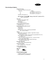
Страница 32: ...w Pressure Remote Set point Current 0 20mA across 600OHM Max isolated to 500Vac Outputs Relay SPST 1A 250 Vac resistive 1A 250 Vac inductive Pilot Duty Rating 125VA Hi Lo Heat Cool Alarm Purge Pump Vent adjustable off to 5 min SSR 1A 250Vac isolated to 1500 Vac Hi Lo Heat Cool Current 0 to 20 mA across 600 ohms max isolated to 500 Vac Heat Cool Process Output Communications RS232 RS485 Half and Fu...

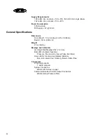
Страница 33: ...2 86 cm Depth 3 3 4 in 8 89 cm Weight 20 oz 622 g Displays and Indicators 2 3 Digit Red Displays 0 56 1 42 cm Red LED s for alarm functions Pressure Thermo Hi Lo Temp Probe Fail Motor Green LED s for status and display indication Run Hi Lo Heat Cool Delivery Return Delta Flow Connectors PCB Interconnects T and B Jumpers System Connectors WAGO 231 Series or equal Communication and Current Output Co...

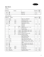
Страница 34: ...oportional Band 2 deg or counts 20 10 rES 0 to 999 9 Reset time in sec 1 5 1 5 OFS 0 to 99 9 Manual reset value in percent OFF OFF rtE 0 to 99 99 Rate time in minutes 0 05 0 05 SLO Slow response process nor Normal response process FAS Fast response process FPC 0 to 100 Fuzzy intensity in percent 0 off Impact fuzzy logic has on process 50 50 Fbd 1 to 400 Fuzzy Band in deg or counts to PBH 14 14 FrC...

Страница 35: ...e for viewing changing OFF OFF StA On OFF note 2 Status of Prog in Home Position OFF OFF SEC 1 S 6OS note 2 Prog time base 1 or 60 sec 1 S 1 S ti 0 to 9999 note 2 Segment time 0 0 SP note 2 Segment Set Pt 0 0 A1 On OFF note 2 Alarm 1 Event OFF OFF A2 On OFF note 2 Alarm 2 Event OFF OFF End Hld Oof LoP SPt note 2 Programmer End Hold Off Loop SP OFF OFF A2L Alarm 2 Low A2H Alarm 2 High Ato On OFF Au...

Страница 36: ... On OFF Safety Thermo On OFF ON ON PrS On OFF Pressure Input On OFF ON ON InP J CA E T C Input Type J K E J J Int OFF 0 1 to 540 0 Input Fault Timer min OFF OFF Ot1 Output 1 type OnF On OFF S1d On OFF differential 1 to 80t Time proportioning cycle rate in sec 20 20 PuL 1 to 7 Pulse curve value 1 linear 7 most non linear PrP Voltage Current proportional output Ot2 Output 2 type OnF ON Off S2d On Of...

Страница 37: ... 0 S2H 10 to 102 Output 1 high limit 100 100 S2C O on oFF Lamp on off contact closed Oon Oon AL2 OFF Lo Hi HL Eut Alarm Off Low High Hi Lo Event OFF OFF A2t AbS dE Absolute or Deviation to SP1 dE dE A2r OnF HOL Alarm Reset On Off Hold OnF OnF A2i On OFF Power Interrupt OFF OFF A2H On OFF Power Inhibit On On A2S CLS OPE Contact Closed Open Alarm CLS CLS A2C O on oFF Lamp on off contact closed Oon O...

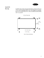
Страница 38: ...m high see Figure 5 Four mounting holes are spaced 7 in 17 78 cm horizontally and 5 in 12 7 cm vertically in a rectangular layout The mounting holes are 1 4 in 6 35 mm diameter and the bolts are size 10 or equivalent Figure 5 Mounting Dimensions 8 1 2 21 59 cm 7 17 78 cm 4 1 2 11 43 cm 5 12 7 cm 1 4 6 35 mm dia ...

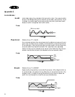
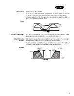
Страница 39: ...l to the deviation This proportional action is active within a zone around the set point called the proportional band The output becomes gradually smaller as the process variable nears the set point Note that the process seldom reached the set point but stabilizes at some deviation offset Temp Integral Referred to as I or RESET Expressed by integral time in seconds the purpose of the integral acti...

Страница 40: ...eset Windup This function inhibits the integral action until the process variable is within the proportional band thus reducing overshoot on start up Direct Reverse Action Direct action is used for cooling applications The output of the controller increases with respect to an increase in the process value Reverse action is used for heating applications The output of the controller decreases with r...

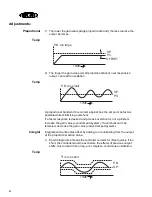
Страница 41: ...s overshoot is not a problem increase the gain value over damped system If overshoot can t be tolerated decrease the gain value under damped system Integral Integral action eliminates offset by adding to or subtracting from the output of the proportional action alone 1 Short integral time means the controller corrects for offset quickly If too short the controller would react before the effects of...

Страница 42: ...k to set point without overshoot Derivative action corrects for disturbances providing sudden shifts in output which opposes the process disturbance Temp 1 A short derivative time means little derivative action If the derivative is too short the controller would not react quickly to process disturbances and may not attain set point 2 A long derivative time means more derivative action If the deriv...

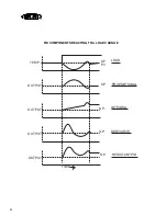
Страница 43: ...42 TEMP TIME S P P V LOAD S P S P S P S P PROPORTIONAL INTEGRAL DERIVATIVE RESULTANT PID OUTPUT OUTPUT OUTPUT OUTPUT PID COMPONENTS REACTING TO A LOAD CHANGE ...

Страница 44: ...tart Seg SEG7RAMP Ramp Time 7 END SEG End Seg SEG8 SP Soak SP 8 RECYCLES Number of Recycles SEG8TIME Soak Time 8 SOAK DEV Deviation Value SEG9RAMP Ramp Time 9 SEG1RAMP Ramp Time 1 SG10 SP Soak SP 10 SEG2 SP Soak SP 2 SG10 TIME Soak Time 10 SEG2TIME Soak Time 2 SG11 RAMP Ramp Time 11 SEG3RAMP Ramp Time 3 SG12 SP Soak SP 12 SEG4 SP Soak SP 4 SG12 TIME Soak Time 12 SEG4TIME Soak Time 4 STATE Program ...

Страница 45: ... output relative to the setpoint Bias Allows the operator to compensate for any difference between sensor temperature and the point to be measured The process display and setpoint will be offset by the value entered in the Bias parameter in the input menu Example Desired temperature is 150 degrees Sensor is adjacent to heater and reads 50 degrees higher than the actual process temperature Enter bi...

Страница 46: ... zero Filtering in Input Menu Sets the time period over which the process value is averaged Hysteresis In on off temperature control hysteresis represents the band where the output changes state from deactivated to activated It prevents chattering around the setpoint and prevents rapid output cycling Hold The freezing of a running program in time for the duration of the condition Integral Automati...

Страница 47: ... The PID parameters are automatically calculated for a particular application during the autotune process Applications for PID Control 1 Where process temperature lags exist 2 When load changes are present 3 When overshoot is prohibited 4 When very accurate control is required Program A preset profile of the controller setpoint made up of ramps and soaks together with the sequence of state of the ...

Страница 48: ... gain for optimum control are calculated and written into the commissioning mnemonics Soak A time entered into a program during which the setpoint remains constant Temperature Lag The product of thermal resistance and thermal capacity Also defined as delay of the transmission of heat from the controlled element to the sensor caused by thermal mass of the process material and or process container o...

Страница 49: ...48 ...
Отзывы: