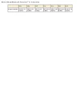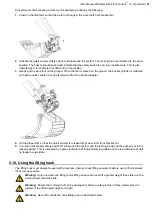
4.3. Technical data - weights and dimensions
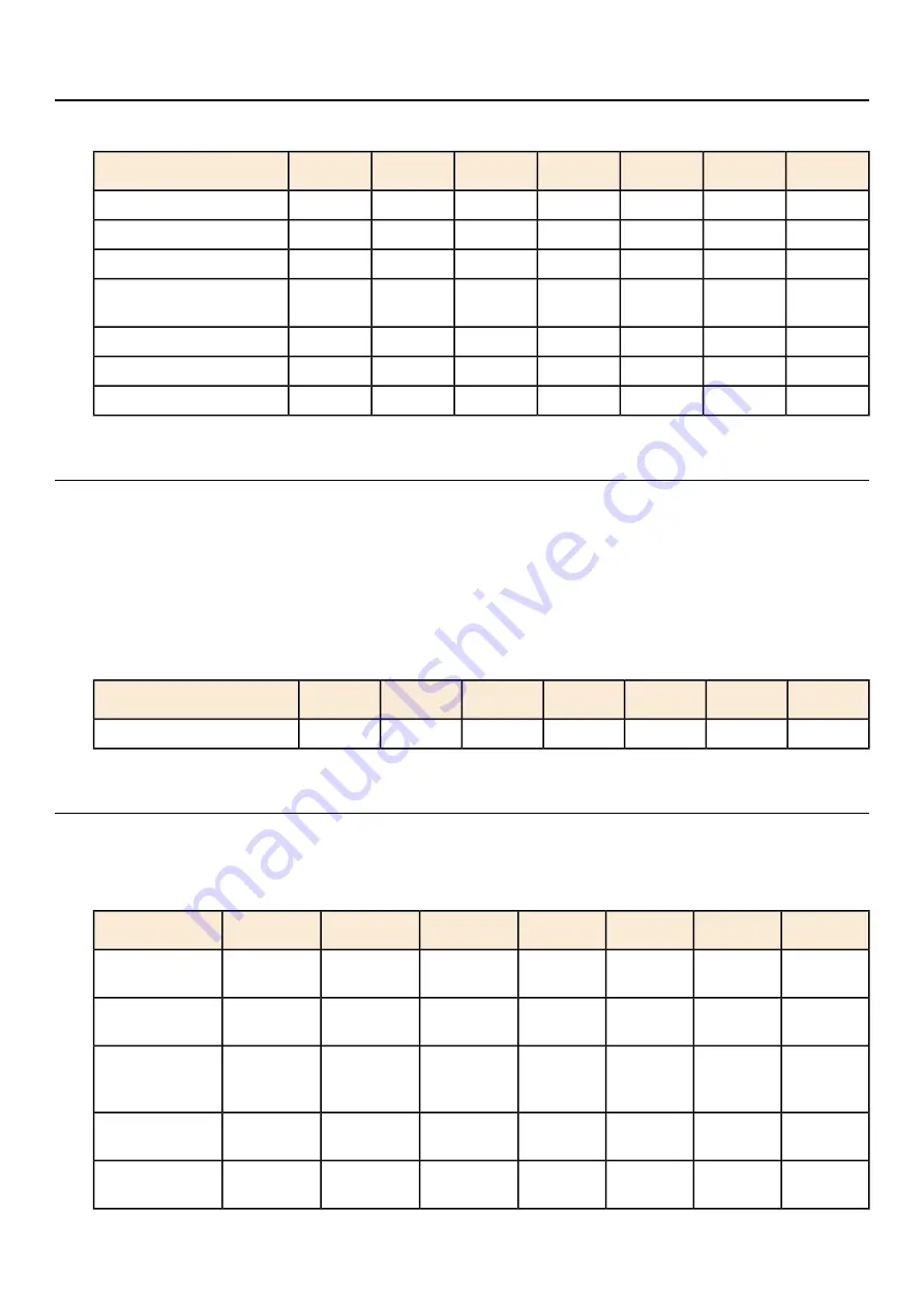
Table 4: Weights and dimensions
X26
X20
X18
X12
X07
X06
X04
690
690
612
564
354
314
314
A. Width (mm)
852
816
726
625
599
505
488
B. Length (mm)
512
508
449
425
391
318
308
C. Building height (mm)
811
710
729
663
556
428
416
D. Width upper section
(mm)
570
445
400
285
195
135
115
Weight from (kg)
61
47
41
29
21
16
16
Tilt Torque (kNm)
10,6
9,0
7,8
6,5
5,3
4,2
3,9
Rotation torque (kN)
4.4. Technical data - gripper cassette
The gripper unit is an option designed to be used for easier gripping and handling jobs within the allowable load
capacity of your excavator. If the gripping unit's maximum lifting capacity exceeds the machine's lifting capacity,
the lowest figure of the two is the maximum lifting capacity.
The gripper unit maximum lifting capacity is calculated when lifting the load where the load rests against the gripper
support plate and the arms grips around the entire object. If the load is lifted in an offset position (for example, at
the point of the gripper arm) the lifting capacity is reduced by 50%. The gripper arms must not be subjected to
greater force than the maximum lifting capacity.
Table 5: Lift Weights
X26
X20
X18
X12
X07
X06
X04
1200
900
900
500
500
350
350
Max Lift Weight (kg)
4.5. Tightening torque
The table below gives the recommended tightening torques for different mounting screws. Certain screw dimensions
can be found in different versions and can be identified by the colors: 12.9 is black, Geomet is gray and A4 is silver.
Table 6: Recommended tightening torque
X26
X20
X18
X12
X07
X06
X04
M10 (12.9)
79Nm
M10 (12.9)
79Nm
M10 (12.9)
79Nm
M10 (12.9)
79Nm
M6 (12.9)
17Nm
M6 (12.9)
17Nm
M6 (12.9)
17Nm
Top cover
M12 (A4)
76Nm
M12 (A4)
76Nm
M12 (A4)
76Nm
M12 (A4)
76Nm
M8 (12.9)
40nm
M8 (12.9)
40nm
M8 (12.9)
40nm
Worm flange
M12 (12.9)
136Nm
M12 (12.9)
136Nm
M12 (12.9)
136Nm
M12 (12.9)
136Nm
M8 (12.9)
40Nm M10
(12.9) 79Nm
M8 (12.9)
40Nm M10
(12.9) 79Nm
M8 (12.9)
40Nm M10
(12.9) 79Nm
Motor screws
M16 (12.9)
333Nm
M16 (12.9)
333Nm
M16 (12.9)
333Nm
M16 (12.9)
333Nm
M12 (12.9)
136Nm
M12 (12.9)
136Nm
M12 (12.9)
136Nm
Tilt cylinder
holder
M18 (12.9)
463Nm
M18 (12.9)
463Nm
M18 (12.9)
463Nm
M16 (12.9)
333Nm
M16 (12.9)
333Nm
M16 (12.9)
333Nm
M16 (12.9)
333Nm
Gear wheel
User Manual tiltrotator with Front pin lock
™
| 4. Technical data |
29
Содержание Tiltrotator Front pin lock X04
Страница 1: ...User Manual Tiltrotator Front pin lock X04 X06 X07 X12 X18 X20 X26 XControl G2 DocNo 700347ENA ...
Страница 2: ......
Страница 3: ...User Manual Tiltrotator Front pin lock X04 X06 X07 X12 X18 X20 X26 XControl G2 DocNo 700347ENA ...
Страница 16: ......
Страница 26: ......
Страница 48: ......
Страница 54: ......
Страница 55: ...Chapter 8 8 Environmental aspects Topics Environmental information ...
Страница 63: ......
Страница 64: ...Steelwrist AB Bäckvägen 18 192 54 Sollentuna Sweden 46 626 07 00 www steelwrist com 700347ENA ...

