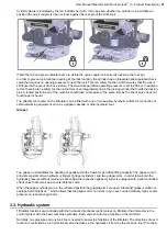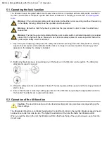
Cylinder status is indicated by the red indicator bar (left). It can be seen whether the cylinder is in a withdrawn
position (the quick coupler is open or locks against the rear pin of the work tool).
If both the red and green indicator bars are visible the quick coupler is incorrectly locked to the rear pin.
In order to prevent unintentional opening of the lock function, the cylinder has an integrated pilot-operated check
valve that requires an opening pressure to open the lock. This is a safety function which ensures that the lock is
still locked in the event of a hose rupture. The maximum permitted operating pressure is set to 250 bar. In addition
to this, there is also a safety function in the form of an integrated spring in the locking cylinder that holds the locking
pins in locked position even if the machine should lose oil pressure at the same time as the check valve does not
function as it should.
The attachment coupler on the tiltrotator can be fitted with one or two auxiliary hydraulic outlets for connection of
external working equipment, such as a gripper cassette or other hydraulic tool.
Gripper:
The gripper unit facilitates the handling of goods within the frame for permitted lifting capacity. The gripper unit in
principle consists of two hydraulic cylinders (”gripper cylinders”) and two gripper arms. In order to maintain the
hydraulic pressure without continuous active flow the respective gripper cylinder is equipped with a pilot controlled
check valve that serves as a counterbalance valve.
When the gripper cylinders are in the retracted position the gripping arms are open. Steelwrist gripper solution is
equipped with GripSync
™
which allows that the gripper arms can work in sync even under relatively high counter
pressure on respective grab arm.
3.3. Hydraulic system
Tiltrotator functions are controlled with the hydraulic directional control valves on tiltrotator that interacts via the
control system with the basic machine hydraulics. Each valves control one function on the manifold.
Normally, one pressure and one tank line is needed to power the functions of the tiltrotator. The directions of each
function is controlled by a 4:3 directional valve that takes in the hydraulic oil from the the pressure line (P) to the A
User Manual tiltrotator with Front pin lock
™
| 3. Product Description |
21
Содержание Tiltrotator Front pin lock X04
Страница 1: ...User Manual Tiltrotator Front pin lock X04 X06 X07 X12 X18 X20 X26 XControl G2 DocNo 700347ENA ...
Страница 2: ......
Страница 3: ...User Manual Tiltrotator Front pin lock X04 X06 X07 X12 X18 X20 X26 XControl G2 DocNo 700347ENA ...
Страница 16: ......
Страница 26: ......
Страница 48: ......
Страница 54: ......
Страница 55: ...Chapter 8 8 Environmental aspects Topics Environmental information ...
Страница 63: ......
Страница 64: ...Steelwrist AB Bäckvägen 18 192 54 Sollentuna Sweden 46 626 07 00 www steelwrist com 700347ENA ...

