INSTALLATION AND OPERATING
INSTRUCTION MANUAL
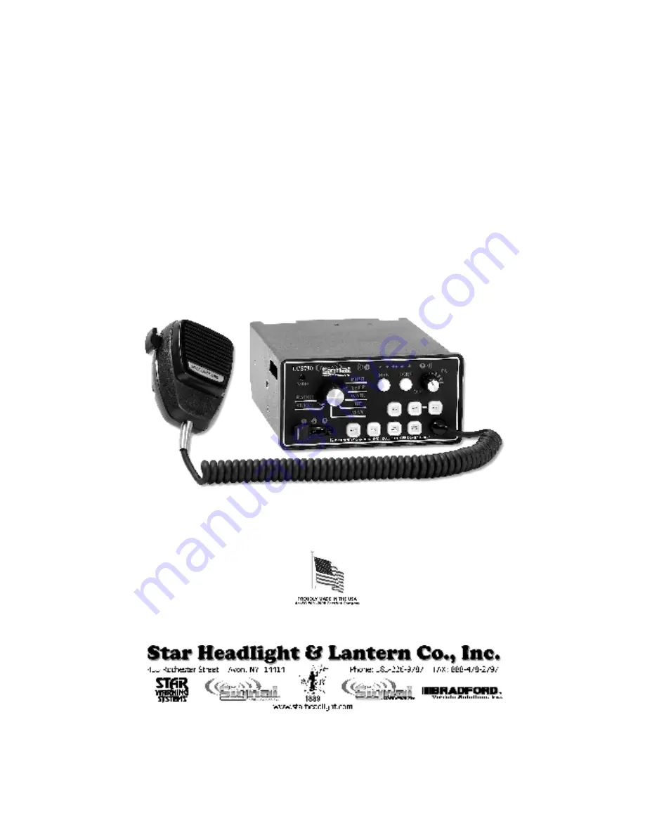
LCS790
SIREN AMPLIFIER & LIGHT CONTROLLER
US PATENT D574,799
PLIT411 REV. - 9/23/08
Страница 1: ...INSTALLATION AND OPERATING INSTRUCTION MANUAL LCS790 LCS790 LCS790 LCS790 SIREN AMPLIFIER LIGHT CONTROLLER US PATENT D574 799 PLIT411 REV 9 23 08...
Страница 2: ...FORMATION PURCHASE DATE INSTALLATION DATE INSTALLER DEALER MODEL LCS790 AMPLIFIER SERIAL NO CONTROL HEAD SERIAL NO ARROWSTICK CONTROL SERIAL NO Model and serial number located on bottom of unit Instal...
Страница 3: ...41 46 ON OFF 41 SELECTOR SWITCH ROTARY KNOB 42 SLIDE SWITCH 43 PUSH BUTTON SWITCHES 43 MANUAL AND HORN BUTTONS 44 Chart of Manual Tones 44 VOLUME CONTROLS 45 MICROPHONE 45 SPEAKER DIAGNOSTICS 45 AUXI...
Страница 4: ...Radio and PA volume controls are provided on the front panel Also located on the front panel are two LED s for speaker diagnostics This unit additionally contains several distinct controls for operat...
Страница 5: ...connect power when installing or uninstalling this device Never use a battery charger to bench test this device This product is intended to be installed and operated in interior applications only Keep...
Страница 6: ...y switch Radio Alert Manual HF Wail Yelp Phaser Push Button Manual and Horn switches Auxiliary input DIP switch programmable for positive or negative horn Remote Manual or Hands Free operation Park Ki...
Страница 7: ...o installation of the siren DIP Switch Settings Option Default Setting Optional Setting Keypad Beep Enabled Silent Gun Lock Mode Disabled 8 sec Open S5 S6 S7 Traffic Director Mode Enabled No Traffic D...
Страница 8: ...l of these switches is down closer to the circuit board The other set contains two DIP switches that slide in or out The default position for these two switches is out towards you Please review the di...
Страница 9: ...ion 3 Siren auto activated in WAIL mode when slide switch is in position 3 Neither the Traffic Director nor the siren is auto activated when slide switch is in position 3 5 AUX AUX Wire Function AUX w...
Страница 10: ...button See page 14 for detailed instructions on how to change the Gun Lock button to a different button to program additional buttons to act as Gun Lock buttons or to change the Gun Lock Timer to 20...
Страница 11: ...ector and siren individually AUX Auxiliary Input Function The auxiliary input terminal 5 of the 10 terminal connector see page 38 allows you to either activate the Air Horn or to mimic the Manual butt...
Страница 12: ...his DIP switch in switch 2 in the diagram above AUX Auxiliary Input Polarity The auxiliary input terminal 5 of the 10 terminal connector and described on the previous page is normally activated by con...
Страница 13: ...Siren Auto Activation Phaser Tone Disabled Any Button s or Slide Switch Tone Change Allowed While In Audible Pursuit Allowed Not Allowed Slide Switch Position 1 Auto Activates Any Button or Slide Pos...
Страница 14: ...S6 S5 S4 S3 S2 S1 NONE YELP ANY Park Kill Deactivation of Functionss 3 3 3 3 1 1 1 1 2 2 2 2 S7 S6 S5 S4 S3 S2 S1 NONE WAIL ANY Advanced Siren Auto Activation WAIL Tone 3 3 3 3 1 1 1 1 2 2 2 2 S7 S6...
Страница 15: ...n Pressing each button once will turn them ON and close the connection apply 12VDC Pressing each button again will turn them OFF and open the connection again If you would like any of these switches t...
Страница 16: ...lip the PGM DIP switch down to save the changes Push Button State At Power Up Each button by default operates as a standard switch When the LCS790 unit is powered up they are all in the OFF mode Press...
Страница 17: ...switch Button is Red Default setting for S4 The button will now operate as a timed Gun Lock switch Each button S1 S7 can be programmed independently of the others Once you have programmed your option...
Страница 18: ...If you would like the unit to beep every 10 seconds when any function is active change this setting Place the PGM DIP switch in this position Up Place the Rotary Knob in this position Alert Place the...
Страница 19: ...switch in this position Up Place the Rotary Knob in this position WAIL Place the Slide Switch in this position 2 2 2 2 And toggle any of these buttons S1 S7 Button is Green Default setting Output if...
Страница 20: ...first placed in HF mode no sound will be produced By default activating the Auxiliary input see page 37 of the Electrical Connections section will produce the WAIL tone Activating the Auxiliary input...
Страница 21: ...function always available S7 is Red Siren will only operate if any of the buttons or slide switch programmed below are activated By default any Slide position other than off will allow for operation o...
Страница 22: ...vates the functions connected to both and 2 2 2 2 Position will activate all of the functions connected to 2 2 2 2 and as well as activating any other Pursuit Mode functions you may program You can ch...
Страница 23: ...DIP switch down to save the changes Slide Switch Positions for Auto Activation of Traffic Director If you have the Auto Activation feature enabled as described above you can select or deselect which s...
Страница 24: ...S4 If S4 is Red Default setting The siren will automatically activate whenever the unit is in Pursuit mode slide switch moved to Position 3 3 3 3 If S4 is Green The siren will NOT activate automatica...
Страница 25: ...of the WAIL tone WAIL To program auto activation of the YELP tone HF To program auto activation of the PHASER tone MAN And toggle any of these buttons S1 S7 HORN MAN Buttons S1 S7 are used to program...
Страница 26: ...ition You may wish to have one or more of the functions that are connected to your push button switches and or slide switch outputs auto activate with your slide switch This unit gives you the ability...
Страница 27: ......
Страница 28: ...rminals Use 8 AWG Lights connected to S1 S7 outputs 12VDC for Backlighting to Terminal 2 of 10 way conn Ignition switched 12VDC to Terminal 7 of 10 way conn Speaker and connected Correct AUX and Park...
Страница 29: ...ITION SWITCHED 12VDC TURNS UNIT ON OFF RADIO AUXILIARY FROM HORN SWITCH 12VDC FOR BACKLIGHTING RADIO PARK KILL HORN OUT TO HORN POWER FOR LIGHTS WARNING LIGHT OUTPUTS 12AWG 18AWG Depending Upon Load P...
Страница 30: ......
Страница 31: ...auto activate with slide switch position 3 3 3 3 Please note the the HORN button will program SS1 output to activate in 3 3 3 3 and the MAN button will program the SS2 output to activate in 3 3 3 3 On...
Страница 32: ...e functions tied to Slide Switch Position 2 2 2 2 will also activate Moving the rotary knob to the PHSR tone will then activate the functions tied to Slide Switch Position 3 3 3 3 To enable this featu...
Страница 33: ...ark Kill function is activated HORN is Green Default setting Functions tied to SS3 3 3 3 output will NOT automatically deactivate whenever the Park Kill function is activated MAN is Green Default sett...
Страница 34: ...Tone or the European sound Once you have programmed your option s to the desired setting s you must flip the PGM DIP switch down to save the changes Phaser Tone Disable As mentioned above by default t...
Страница 35: ...ivating HRT is acceptable you can flip the PGM DIP switch down to save the changes and skip the Advance Slide Switch Programming section below Advanced Slide Switch Programming If you need to select w...
Страница 36: ...output when any function is activated on this unit If S4 is Red The Action output will pulse 12VDC output when any function is activated on this unit Once you have programmed your option s to the desi...
Страница 37: ...guration 1 Stick operated with 3 wires Warn Left and Right Warn S5 Left S6 Right S7 and Center Out Press S6 S7 C O activated by power to only Left Right wires from stick Alt TD Configuration 2 Stick o...
Страница 38: ...rn You must hold the Manual and Horn but tons for approximately 15 seconds to reset the siren The five amber traffic director LEDs will sequentially light up from left to right while you are holding d...
Страница 39: ...ers can cause permanent hearing loss Never operate this unit without adequate hearing protection for you and others in the area OSHA 1910 95 The LCS790 siren may be mounted above the dash below the da...
Страница 40: ...n Please review pages 34 and 39 to determine the minimum wire size used for each connection Please also use the following guidelines when wiring your siren Use only high quality crimp connectors Make...
Страница 41: ...s for the audio functions and up to 100 amps for the additional devices and or lights you have connected to the outputs The preferred source is directly at the vehicle battery The slide switch push bu...
Страница 42: ...output is generally used to automatically trigger a device such as a video camera when any functions on this unit are switched on While any functions are active this terminal will output 12 VDC A devi...
Страница 43: ...other 1A Device to be Auto activated with all switches S3 20A MAX CAUTION Do not connect devices that draw more than 100A combined total for all the outputs Connect to device to be controlled by S4 U...
Страница 44: ...the dash lights parking lights or other switched source Be sure to use minimum size 18 AWG wire Note The unit will still function without power to this wire There will not be any backlighting though...
Страница 45: ...t has the vehicle s horn switch disconnected from the horn and routed to the Auxiliary terminal see the Wiring Diagram on page 39 Use 18 AWG wire Ignition Switched Terminal 7 Use an 18 AWG wire to con...
Страница 46: ...1 18 AWG BACKLIGHTING 18 AWG AUXILIARY 18 AWG RADIO 2 18 AWG RADIO Door Switch 12 VDC Siren Wiring Diagram 2 IGNITION SWITCHED 12VDC 18 AWG SPEAKER 1 14 AWG SPEAKER 2 14 AWG SPEAKER COMMON 14 AWG Top...
Страница 47: ...es The product is shipped with 49 different labels for these push buttons Select the desired label inserts Insert the label into each button and tuck it under the lip of the switch Testing Test all si...
Страница 48: ...PA will both turn the siren unit on and off as well as control the public ad dress volume It is located in the upper right hand corner of the front face When the unit is not in use you may elect to le...
Страница 49: ...tton is released or can optionally sweep tones see the Detailed Programming section on page 17 ALERT A silent mode that allows push button Manual push button Horn and Public Address operation The diff...
Страница 50: ...everal settings related to the slide switch including Push Button Switches S1 S7 Seven push button switches are provided to operate your external lights or devices Each push button S1 S7 will control...
Страница 51: ...LO or disabling the Phaser tone entirely see page 27 of the Detailed Programming section These options may be governed by State and or Local laws NOTE PHASER and TWO TONE may be optionally swapped or...
Страница 52: ...t clicks This will power down the unit and will prevent accidental activation of any of the controls on the face of the unit Rotating it clockwise will power up the LCS790 As it is turned clockwise th...
Страница 53: ...tore normal function See the Installation Wiring section on page 37 for details Fuses The outputs on this unit are protected by ten 20 Amp automotive type blade fuses They are located on the bottom of...
Страница 54: ...High voltage protection Low voltage protection Microphone button activation Circuit breaker in supply connection Shorted speaker or speaker wire Is the vehicle voltage regulator working properly Is t...
Страница 55: ...r from the date of delivery to the first user purchaser During this warranty period the obligation of Signal Vehicle Products is limited to repairing or replacing as Signal Vehicle Products may elect...
Страница 56: ...ps within the warranty period please con tact our Customer Service Department at 585 226 9025 When contacting us about a product you have purchased please have the product s serial number readily avai...