Page 09
4 - Operation
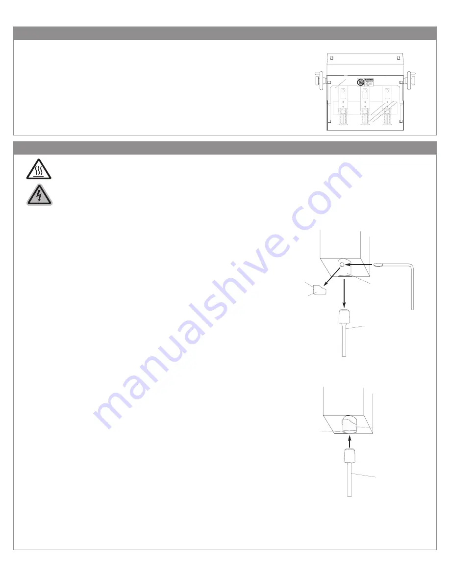
4.1 - Protective Guard
4.2.1
4.2.2
4.2.3
4.2.4
4.2.5
4.2.6
4.2.7
CAUTION: DRILL BITS MAY BE HOT AFTER USE. ALLOW DRILL BITS TO COOL
DOWN BEFORE TOUCHING.
BEFORE REMOVING OR INSTALLING THE DRILL BITS, DISCONNECT OR
LOCK-OUT THE POWER SUPPLY TO THE DRILL MOTOR.
4.2 - Drill Bit Removal and Installation
Diagram 4-10
4.1.1
4.1.2
We recommend using a piece of card stock on the Table when
leveling the drill bit to avoid drilling into the drill strip. This will
lengthen the life of your drill bits and keep them sharper.
Remove the hole guard which is attached to the chuck. This is
done by grasping the tab and sliding the guard off.
Using the Chuck Release Key (EBM-32), insert the tapered end
facing down into the chuck hole. In a clockwise motion turn the
Chuck Release Key 45 degrees. The drill bit will slide out of the
chuck. It is recommended that you hold onto the drill bit so that it
does not drop out of the chuck damaging the tip.
To install a drill bit, grasp the drill bit, and being careful to keep it
straight, press it up into the chuck.
Seat the drill bit by using a stack of scrap paper. Set the scrap on
the table. Lower the table lift speed by turning the Table Adjust-
ment Knob (see section 4.9). Step on the foot pedal slowly rais-
ing the table toward the Drill Bit. Put light pressure on the hollow
Drill Bit seating it firmly in place.
Remove the scrap paper and turn the machine on to check the
concentricity of the bit. If the bit is not concentric, remove it and
repeat steps 4.2.2 through 4.2.5 until it is concentric.
When the drill bit is correctly installed replace the hole guard back
onto the chuck to protect debris from clogging the chuck.
Diagram 4-20
Chuck
Hole Guard
Drill Bit
Chuck Release Key
Tab
Chuck
Hole Guard
Drill Bit
Diagram 4-30
Your FMMH-3.1 comes with a protective guard installed. DO NOT
operate this machine without the guard in place.
Please note that when you are performing certain operations such
as removing and installing drill bits, you will need to move the
guard out of the way. Making sure the power to the machine is
disconnected or locked-out, push the guard up and hold in place
while performing necessary operations or maintenance. The pro-
tective guard should not be removed during operation.
Содержание FMMH 3.1
Страница 4: ...2 Safety 2 2 Warning Labels Page 03 WARNING DO NOT EXPOSE TO RAIN OR USE IN DAMP LOCATIONS...
Страница 20: ...7 Parts Diagrams 7 1 Side View Page 19...
Страница 21: ...7 Parts Diagrams 7 2 Head Assembly Page 20...
Страница 22: ...7 Parts Diagrams 7 3 Spindle and Chuck Assembly Page 21...
Страница 23: ...7 Parts Diagrams 7 4 Rear View Page 22...


