Section 5: Service Information
Page 5-2
NetClock/GTP Instruction Manual
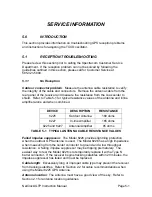
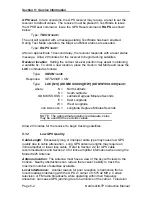
GPS reset
: In rare occasions, the GPS receiver may require a reset to set the
receiver to default values. The receiver must be placed in Test Mode to issue
the GPS Reset command. Issue the GPS Reset command,
RGPS
, as shown
below:
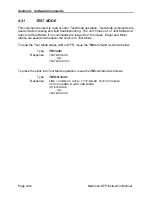
Type:
TM ON <ent>
The unit will respond with a message stating Test Mode has been enabled.
During Test Mode operation, the Major and Minor alarms are asserted.
Type:
RGPS <ent>
After an approximate 10 second delay, the receiver responds with a reset status
message. Allow 20 minutes for the receiver to begin tracking satellites.
Receiver location
: Setting the current receiver position may assist in obtaining
a satellite fix. To enter a new location, place the clock in
Set Mode
and issue the
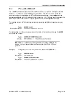
LOC
command as follows:
Type:
SM ON <ent>
Response:
SET MODE = ON
Type:
LOC [N:S] [DD MM SS.SSS][E:W] [DD MM SSS.SSS]<ent>
where:
N =
North Latitude
S =
South Latitude
DD MM SS.SSS =
Latitude Degrees:Minutes:Seconds
E = East Longitude
W =
West Longitude
DDD MM SS
.
SSS
= Longitude Degrees:Minutes:Seconds
NOTE: The approximate location is adequate, zeros
may be used for the seconds values.
Allow 20 minutes for the receiver to begin tracking satellites.
5.1.2
Low GPS Quality
Cable Length
: Excessively long or improper cable type may cause low GPS
quality due to cable attenuation. Long GPS antenna lengths may require an
inline amplifier or lower loss cable. Refer to Section 2.2 for GPS cable
recommendations and Section 2.4 for inline amplifier information when using the
Model 8225 Antenna
Antenna location
: The antenna must have a view of the sky with views to the
horizon. Nearby obstructions can reduce the receiver's ability to track the
maximum number of satellites available.
Local Interference:
Another reason for poor reception is harmonics from a
local broadcast interfering with the GPS L1 carrier of 1575.42 MHz. Certain
television or FM radio broadcasts, while operating within their frequency
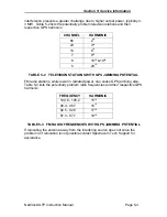
allocation, can cause GPS jamming due to harmonics of the carrier. Television
Содержание 8183A GTP
Страница 36: ...Section 3 Operation Page 3 2 NetClock GTP Instruction Manual FIGURE 3 1 NETCLOCK GTP FRONT PANEL...
Страница 39: ...Section 3 Operation NetClock GTP Instruction Manual Page 3 5 FIGURE 3 2 NETCLOCK GTP REAR PANEL...
Страница 64: ...SECTION 4 SOFTWARE COMMANDS 4 0 INTRODUCTION 4 1 4 22 RS 232 COMMAND SET...
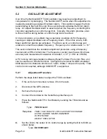
Страница 96: ...SECTION 5 SERVICE INFORMATION 5 0 INTRODUCTION 5 1 RECEPTION TROUBLESHOOTING 5 2 TCXO ADJUSTMENT...
Страница 102: ...APPENDIX A IRIG CODE DESCRIPTION A 0 INTRODUCTION A 1 FAA IRIG B CODE...
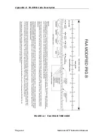
Страница 104: ...Appendix A FAA IRIG Code Description Page A 2 NetClock GTP Instruction Manual FIGURE A 1 FAA IRIG B TIME CODE...


