Section 3: Operation
NetClock/GTP Instruction Manual
Page 3-25
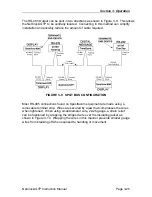
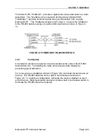
The RS-485 Output can be split in two directions as shown in Figure 3-9. This allows
the NetClock/GTP to be centrally located. Connecting in this method can simplify
installation and possibly reduce the amount of cable required.
FIGURE 3-9 SPLIT BUS CONFIGURATION
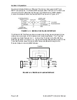
Most RS-485 connections found on Spectracom equipment are made using a
removable terminal strip. Wires are secured by a jaw that compresses the wires
when tightened. When using small diameter wire, 22-26 gauge, a strain relief
can be fashioned by wrapping the stripped wire over the insulating jacket as
shown in Figure 3-10. Wrapping the wires in this manner prevents smaller gauge
wires from breaking off when exposed to handling or movement.
Содержание 8183A GTP
Страница 36: ...Section 3 Operation Page 3 2 NetClock GTP Instruction Manual FIGURE 3 1 NETCLOCK GTP FRONT PANEL...
Страница 39: ...Section 3 Operation NetClock GTP Instruction Manual Page 3 5 FIGURE 3 2 NETCLOCK GTP REAR PANEL...
Страница 64: ...SECTION 4 SOFTWARE COMMANDS 4 0 INTRODUCTION 4 1 4 22 RS 232 COMMAND SET...
Страница 96: ...SECTION 5 SERVICE INFORMATION 5 0 INTRODUCTION 5 1 RECEPTION TROUBLESHOOTING 5 2 TCXO ADJUSTMENT...
Страница 102: ...APPENDIX A IRIG CODE DESCRIPTION A 0 INTRODUCTION A 1 FAA IRIG B CODE...
Страница 104: ...Appendix A FAA IRIG Code Description Page A 2 NetClock GTP Instruction Manual FIGURE A 1 FAA IRIG B TIME CODE...

