Section 3: Operation
Page 3-4
NetClock/GTP Instruction Manual
3.2
REAR PANEL FUNCTIONS
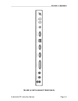
Refer to Figure 3-2, NetClock/GTP Rear Panel, and the following paragraphs for
rear panel functions.
3.2.1 GPS
Antenna
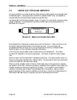
This BNC connector is the antenna input to the GPS receiver. The Model 8225
GPS Antenna and the Model 8227 Inline Preamplifier receive operational power,
+5 VDC, from this connector.
3.2.2
Standard 10 MHz Output
The STD 10 MHz Output BNC connector provides a 10 MHz sinewave derived
from the GPS disciplined TCXO time base. Frequency accuracy is better than 1
x 10
-8
(±0.1 Hz). Signal level is 350 mVrms into 50 ohms. The 10 MHz output
may be used as a time base for signal generators, frequency counters or other
devices accepting an external reference frequency.
3.2.3 1PPS
Output
This BNC connector provides a GPS derived one pulse-per-second output. The
leading edge of this TTL compatible signal is within ± 500 nanoseconds of UTC
with selective availability (SA) on. The leading edge can be adjusted to
compensate for antenna cable delays using the command
ACD
.
Refer to Section 4,
Software Commands
, for additional information on the
ACD
command.
Содержание 8183A GTP
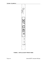
Страница 36: ...Section 3 Operation Page 3 2 NetClock GTP Instruction Manual FIGURE 3 1 NETCLOCK GTP FRONT PANEL...
Страница 39: ...Section 3 Operation NetClock GTP Instruction Manual Page 3 5 FIGURE 3 2 NETCLOCK GTP REAR PANEL...
Страница 64: ...SECTION 4 SOFTWARE COMMANDS 4 0 INTRODUCTION 4 1 4 22 RS 232 COMMAND SET...
Страница 96: ...SECTION 5 SERVICE INFORMATION 5 0 INTRODUCTION 5 1 RECEPTION TROUBLESHOOTING 5 2 TCXO ADJUSTMENT...
Страница 102: ...APPENDIX A IRIG CODE DESCRIPTION A 0 INTRODUCTION A 1 FAA IRIG B CODE...
Страница 104: ...Appendix A FAA IRIG Code Description Page A 2 NetClock GTP Instruction Manual FIGURE A 1 FAA IRIG B TIME CODE...

