Section 2: Installation
NetClock/GTP Instruction Manual
Page 2-13
2.8
QUALIFYING THE INSTALLATION
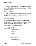
Typically, the front panel TIME SYNC lamp turns green within 20 minutes of power on.
This lamp indicates that receiver is tracking at least one qualified satellite. If the GPS
LOCK lamp does not change from red to green, a cable or reception problem may exist.
Refer to Section 5.1 for troubleshooting assistance.
Reception quality can be evaluated using the performance and status logs provided by
the receiver. Commands to retrieve operational information are issued through the rear
panel RS-232 Serial Setup Interface port. To communicate with the receiver, a terminal
or computer with terminal emulation software (i.e. ProComm Plus, Hyper-Terminal, etc.)
is required. Configure the terminal for ANSI emulation, 9600 baud and a character
structure of 1 start, 8 data, 1 stop and no parity. XON/XOFF flow control is supported.
2.8.1
GPS Signal Status
The
G
PS
S
ignal
S
tatus command,
GSS
, provides an instantaneous view of the GPS
reception quality. This command is used to verify proper antenna placement and
receiver performance of an installation. The GSS response indicates the number of
satellites the receiver is currently tracking and their relative signal strength. The
resulting GPS quality and Position Fix Status are also included. A complete description
of the
GSS
command can be found in Section 4 of this manual.
Issue the GSS command as shown below.
Type:
GSS <ent>
An example response is shown below:
TRACKING 4 SATELLITES
GPS STATE= 3D-FIX DOP= 03.7
LATITUDE= N 43 06 59.746 LONGITUDE= W 077 29 15.242 HEIGHT= +00110 METERS
QUALITY= PASSED
CHAN VID MODE STREN STAT
01 24
08
043 A2
02 04
08
029 A2
03 10
00
000 00
04 05
08
053 A2
05 18
00
000 00
06 30
00
000 00
07 01
08
047 A2
08 06
00
000 00
Содержание 8183A GTP
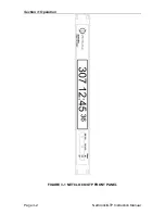
Страница 36: ...Section 3 Operation Page 3 2 NetClock GTP Instruction Manual FIGURE 3 1 NETCLOCK GTP FRONT PANEL...
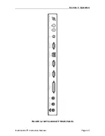
Страница 39: ...Section 3 Operation NetClock GTP Instruction Manual Page 3 5 FIGURE 3 2 NETCLOCK GTP REAR PANEL...
Страница 64: ...SECTION 4 SOFTWARE COMMANDS 4 0 INTRODUCTION 4 1 4 22 RS 232 COMMAND SET...
Страница 96: ...SECTION 5 SERVICE INFORMATION 5 0 INTRODUCTION 5 1 RECEPTION TROUBLESHOOTING 5 2 TCXO ADJUSTMENT...
Страница 102: ...APPENDIX A IRIG CODE DESCRIPTION A 0 INTRODUCTION A 1 FAA IRIG B CODE...
Страница 104: ...Appendix A FAA IRIG Code Description Page A 2 NetClock GTP Instruction Manual FIGURE A 1 FAA IRIG B TIME CODE...


