2-12
PCS-1500/1500P
2-5-8. MA-97 Board
Replacement Part
Part name :
MA-97N board (For NTSC)
MA-97P board (For PAL)
Part number : A-8322-879-A (For NTSC)
A-8322-880-A (For PAL)
Replacement Procedure
1.
Remove the upper cabinet.
(Refer to Section “2-4. Removing the Cabinets”.)
2.
Remove the RX-47 board.
(Refer to Section “2-5-4. RX-47 Board”.)
3.
Remove the IPM-92 board.
(Refer to Section “2-5-5. IPM-92 Board”.)
4.
Remove the IPM-93 board.
(Refer to Section “2-5-6. IPM-93 Board”.)
5.
Remove the DE-54 board.
(Refer to Section “2-5-7. DE-54 Board”.)
6.
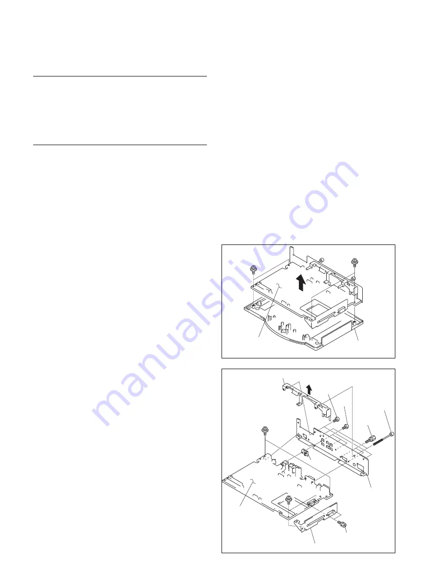
Remove the four screws, and remove the MA-97 board
from the cabinet lower assembly.
2-5. Replacing the Main Parts
7.
Remove the camera retaining screw and the two
screws (B3
x
5) and remove the screw support in the
direction of the arrow.
8.
Remove the two hexagon screws (B3
x
6) and remove
the connector panel.
9.
Remove the two hexagon screws (PSW3
x
6) and
remove the connector side panel.
10. Attach the new MA-97 board by reversing the disas-
sembling procedure of steps 1 to 9.
n
The shield S is attached to the connector CN400 of the
MA-97 board. Be careful not to lose it because it is a small
part.
n
B3
x
6 : Standard tightening torque :
80
x
10
_
2
N
.
m {8 kgf
.
cm}
PSW3
x
6 : Standard tightening torque:
80
x
10
_
2
N
.
m {8 kgf
.
cm}
Hexagon screw : Standard tightening torque :
60
x
10
_
2
N
.
m {6 kgf
.
cm}
PSW3
x
6
PSW3
x
8
MA-97 board
Cabinet lower
assembly
PSW3
x
6
PSW3
x
6
B3
x
6
B3
x
5
Screw support
Hexagon
screw
Camera
retaining
screw
Connector panel
Shield S
Connector side panel
Hexagon screw
MA-97 board
Содержание PCS-1500
Страница 8: ......
Страница 67: ...1 59 PCS 1500 1500P 3 867 901 01 1 1999 Sony Corporation Upgrade Kit Operating Instructions PCS UC150 GB ...
Страница 75: ...1 67 PCS 1500 1500P Sony Corporation Printed in Japan ...
Страница 76: ......
Страница 130: ......
Страница 194: ...4 64 PCS 1500 1500P 4 2 Self diagnostics Function 5 7 CN600 4 A 9 IC604 1 A 7 IC600 5 7 A 10 IC604 3 A 8 CN601 2 A 6 ...
Страница 198: ......


