10
(E)
MJ620
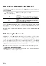
3-4-2. Setting the reference point output signal width
The width of the reference point output signal can be changed by mode switch 1-4 (reference
point mode switch).
MODE switch 1-4
Reference point output signal width
(reference mode switch)
1/4 Z mode
ON
The reference point signal is output in synchronization
when both the A phase and B phase are at the high level.
Z mode
OFF
The reference point signal is output in synchronization
during the one cycle of the A phase.
The reference point output signal is output in both directions with respect to the encoder
travel direction. As a result, differences in the reference point position may occur in the
travel direction.
Be sure to always use in the reading direction of the reference point where the setting has
been made.
3-4-3. Adjusting the reference point
In the MJ620, in order for the interpolator to output reference point signals in synchronization
with the A/B phase output, it is necessary to set the positional relationship between the
encoder and the reference point gate or the sensor or the switch installed at the selected
position. This adjustment and setting is made so that reference point signals can be output at
the same SIN-COS signal reference point in case the reference point position is slightly
displaced due to the temperature and electrical characteristics.
When the positional relationship between the encoder SIN-COS signal and
reference point gate is already known:
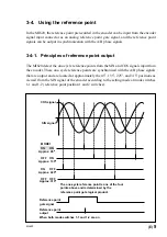
Set MODE switches 1-1 and 1-2 (reference point positions 1 and 2 switches) while referring
to “3-4-1. Principles of reference point output.”


