MJ620
(E)
i
Contents
1. Notes to Users ........................................................... 1
1-1.
General precautions .......................................................................................... 1
1-2.
Precautions ........................................................................................................ 1
1-3.
Installation ........................................................................................................ 1
2. Introduction ............................................................... 2
3. Operation ................................................................... 3
3-1.
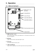
Names of each part ........................................................................................... 3
3-2.
Switches ............................................................................................................ 4
3-3.
Number of divisions and output phase difference ............................................ 6
3-3-1.
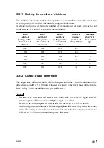
Setting the number of divisions ..................................................... 7
3-3-2.
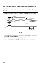
Output phase difference ................................................................. 7
3-3-3.
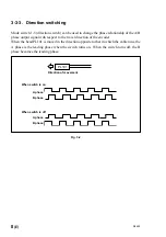
Direction switching ........................................................................ 8
3-4.
Using the reference point .................................................................................. 9
3-4-1.
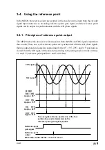
Principles of reference point output ............................................... 9
3-4-2.
Setting the reference point output signal width ........................... 10
3-4-3.
Adjusting the reference point ....................................................... 10
3-5.
Setting the minimum phase difference ........................................................... 12
3-6.
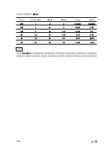
Maximum response speed ............................................................................... 12
3-7.
Alarm signal .................................................................................................... 14
3-7-1.
Alarm reset mode ......................................................................... 14
3-8.
Setting the hysteresis ...................................................................................... 15
3-9.
Power supply ................................................................................................... 16
3-10.
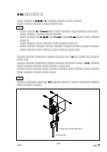
Mounting the interpolator ............................................................................... 17
4. Input and Output Connectors ................................ 18
4-1.
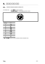
Encoder signal input connector ....................................................................... 18
4-2.
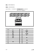
Output connector ............................................................................................. 19
4-2-1.
Output connector .......................................................................... 19
4-2-2.
Input and output cable specifications ........................................... 20
5. Specifications .......................................................... 21
5-1.
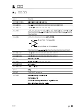
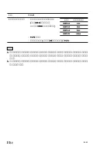
General specifications ..................................................................................... 21
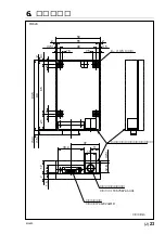
6. Dimensions .............................................................. 23

