(E)
11
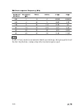
MJ620
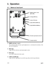
ABS
POS.4
POS.3
POS.2
POS.1
L-AL
S-AL
When the positional relationship between the encoder SIN-COS signal and
reference point gate is not already known:
When the reference point position has been changed after installing an encoder or reference
point sensor, be sure to always use the procedure on the next page to make adjustments and
settings.
1.
Move the encoder in the direction opposite from the reference point reading direction,
and then move the encoder past the reference point. Check that the ABS lamp is off at
this time.
2.
Set mode switch 1-3 (reference point adjustment mode switch) to on. The system changes
to reference point setting mode, and all POS. lamps turn off.
3.
Move the encoder past the reference point. One of the POS. lamps turns on.
4.
Set mode switches 1-1 and 1-2 (reference point positions 1 and 2 switches) according
to the POS. lamp that is lit. (See table 1.)
5.
Set mode switch 1-3 (reference point adjustment mode switch) to OFF.
LED array
.
To increase the accuracy in reproducing the synchronized reference point, be sure that
the encoder passes through the reference point at the same speed when the reference
point was originally set and when detecting the reference point at the beginning of the
work.
Settings
Mode switch 1-1
Mode switch 1-2
POS.4
OFF
OFF
POS.3
ON
OFF
POS.2
OFF
ON
POS.1
ON
ON
Table 1

