

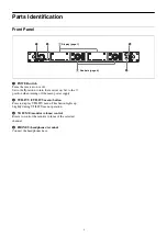
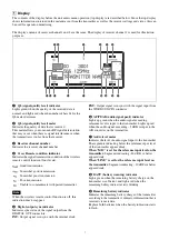


9
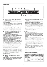
Rear Panel
a
MAIN OUT (main output) (analog output) 1/2
connectors (XLR)
Connect the analog input connector of mixer, amplifier,
or other equipment.
You can use menu operations to set the output level and
to disconnect the XLR connector grounding (pin 1) and
the chassis grounding.
b
SUB OUT (sub output) (digital / analog output)
1/2 connectors (XLR)
Outputs AES3-format digital audio signals or analog
audio. You can switch the output via menu operations.
c
LAN (Ethernet) (10/100/1000) / Dante (Dante
networking) PRIMARY/SECONDARY
connectors (RJ-45)
Use these to establish 1000BASE-T network
connections. Connect to a Windows computer or a hub,
and use Wireless Studio to communicate.
With Dante digital audio supported, redundancy and
headphone monitoring are possible in addition to IP
transmission of multi-channel audio.
Use LAN cables that are Category 5e or higher and 100 m
or less in length. If the distance to the device exceeds 100
m, connect a hub between the unit and the device.
You can specify the signal transmitted from the LAN
connectors according to the UTILITY > NETWORK >
NETWORK MODE setting.
The unit has a switching hub function which allows
operation using a daisy-chain connection when
NETWORK MODE is set to SWITCHED.
When using the headphone monitoring function, connect
each monitored device with both the Dante audio network
and DWX device communication signals, and configure
the identical values for UTILITY > AUDIO >
MONITOR MODE.
d
DIGITAL OUT (digital output) connector
(BNC-R)
These connectors output a digital audio signal in AES3
format. Connect the digital input connector of mixer,
amplifier, or other equipment.
e
ANTENNA a/b IN (antenna a/b input) connectors
(BNC-R)
Connect an optional UHF antenna (e.g., AN-820A) and
the supplied whip antenna to these connectors.
When an antenna is connected, this connector supplies
9 V or 12 V DC power to the booster incorporated in the
antenna. When using an antenna which does not require a
power supply, you can turn off the power output by menu
operation.
When using the AN-820A, you can set the gain of the
booster from the menu of the unit.
• Do not short-circuit this connector.
• When connecting multiple units in cascade, set ANT
ATT a/b to “0dB” and ANT DC OUT to “OFF” on any
DWR-R03D unit that is not directly connected to the
antenna.
About the antenna gain and the cable loss
When the antenna with the booster is connected to the unit
and the antenna gain exceeds the coaxial cable loss
between the antenna and the unit, the RF signal which
exceeds the allowable level may be input to this unit.
To prevent this, set the cable loss and antenna attenuator
(0 dB, 3 dB, 6 dB, 9 dB, 12 dB) to meet the following
equation.
The RF indicator on the receiver lights in orange when the
input becomes 87 dBµ or higher (0 dBµ = 1 µV
EMF
), so
you can use it as a rough guide.
Gain of antenna booster - Cable loss between antenna
and this unit - Antenna attenuator setting (dB) = 0 dB
or less
Reference: Cable loss examples
1
2
3
4
6
5
9
7
0
8
Notes
Type of cable
RG-212/U
RG-213/U
Frequency
600 MHz 800 MHz 600 MHz 800 MHz
Cable
length
50 m
(approx.
165 ft)
12 dB
14 dB
9 dB
11 dB
100 m
(approx.
330 ft)
24 dB
28 dB
18 dB
22 dB


