


27
UTILITY Menu
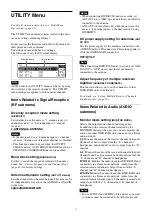
For details on menu operation, see “Basic Menu
Operations” (page 21).
The UTILITY menu includes items related to the basic
receiver settings, including displays.
In this section, the functions included in the menu and
their parameters are explained.
Underlined items are the factory settings.
The following shows the US model display.
All the items in the UTILITY menu can be set by using
the controls on the receiver channel 1. The UTILITY
menu settings are applied to both receiver channels.
Items Related to Signal Reception
(RF submenu)
Diversity reception mode setting
(DIVERSITY)
Set whether to use the unit as a “2-antenna input × 2-
channel receiver” or “4-antenna input × 1-channel
receiver.”
2-ANTENNA/4-ANTENNA
• If the unit is used as a “4-antenna input × 1-channel
receiver,” the function of receiver channel 2 is disabled.
• This function cannot be used when the OUTPUT
SWAP function, AUTO FREQ CHANGE function, or
CHANNEL COORDINATE function is enabled.
Band block setting
(BAND BLOCK)
Set this to match the supported transmitter frequency
bands. See
“Carrier Frequencies and Channel Steps”
Antenna attenuator setting
(ANT ATT a/b/c/d)
Sets the attenuator for the antenna input. This item can be
set independently for each of the ANTENNA a/b/c/d IN
connectors.
0dB/3dB/6dB/9dB/12dB
• When connecting DWR-R03D units in cascade, set
ANT ATT a/b to “0dB” on any unit that is not directly
connected to the antenna.
• ANT ATT c/d is enabled only when the unit is set for
use as a “4-antenna input × 1-channel receiver” using
DIVERSITY.
DC power supply setting for antennas
(ANT
DC OUT)
Sets the power supply for the antennas connected to the
ANTENNA a/b/c/d IN connectors. This setting applies to
all of the ANTENNA IN connectors.
OFF/9V/12V
When connecting DWR-R03D units in cascade, set ANT
DC OUT to “OFF” on any unit that is not directly
connected to the antenna.
Adjust frequency of multiple receivers
together
(CHANNEL COORDINATE)
This function allows you to set the channels of other
DWR-R03D units from this unit.
For details, see “Setting Multiple Receiver Channels
Simultaneously” (page 16).
Items Related to Audio (AUDIO
submenu)
Monitor mode setting
(MONITOR MODE)
Selects the output mode when monitoring audio.
In addition to the receiver channel selected by the
MONITOR button of the unit, you can also monitor the
audio of another DWR-R03D unit connected via a Dante
audio network.
1/2:
Monitor the audio of the receiver channel of the unit.
Channel 1 audio is output from the “L” channel of
headphones, and channel 2 audio is output from the “R”
channel.
1+2:
Monitor the audio of the receiver channel of the unit.
Channel 1 and 2 audio are mixed and output from both the
“L” channel and “R” channel of headphones.
IP SOLO:
Monitor the audio of another DWR-R03D unit
connected via a Dante audio network. Audio from the
selected receiver channel is output from both the “L”
channel and “R” channel of headphones.
IP MIX:
Monitor the audio of another DWR-R03D unit
connected via a Dante audio network. Audio from the
selected receiver channel (up to 8 channels) is mixed and
output from both the “L” channel and “R” channel of
headphones.
• To use IP SOLO and IP MIX, all the devices you want
to monitor must be connected to both the Dante and
Note
Notes
Function name
Item to be set
Notes
Note
Notes


