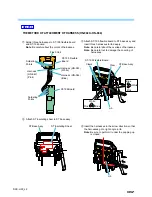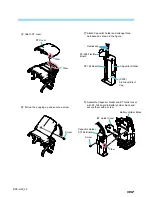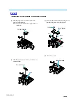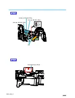
2-4
DSC-H50_L2
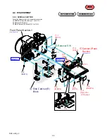
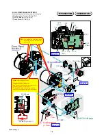
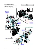
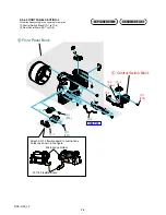
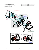
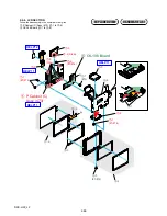
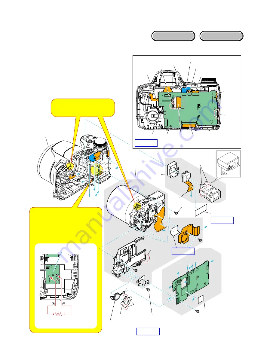
2-2-2. FRONT PANEL SECTION-1
Follow the disassembly in the numerical order given.
1
Loudspeaker (1.3cm) (
1
-1 to
1
-3)
2
SY-201 Board (
2
-1 to
2
-16)
3
Lens Block (
3
-1 to
3
-3)
EXPLODED VIEW
HARDWARE LIST
SY
-201
SY-201
H
G
F
H
G
E
D
C
B
A
J
I
F E
C
A
I
J
H
B
G
D
1
-1
(Claw)
1
-2
1
-3
1
Loudspeaker
(1.3cm)
2
SY-201 Board
3
Lens Block
2
-11
(#76)
2
-12
(Claw)
2
-13
(Claw)
2
-1
2
-5
2
-8
2
-10
2
-9
2
-3
2
-4
2
-6
2
-7
2
-16
2
-15
2
-14
2
-2 (Claw)
3
-1 (#76)
3
-2
(#74)
3
-3 (Claw)
HELP02
HELP04
HELP03
HELP03
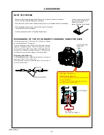
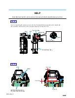
Note: High-voltage cautions
Discharging the Capacitor
Short-circuit between the two points with
the short jig about 10 seconds.
To avoid the spark with the metal plate,
wrap the short jig with the insulation tape.
ST-194 Board
R:1 k
1
/1 W
(Part code: 1-215-869-11)
Note: On installation of the lens block,
adjust the position of the night
shot switch.
Front Panel
Section-2
(See Page 2-5)

