C905
1222-9526 rev. 1
FUNCTIONAL OVERVIEW
FU
N
C
T
IO
N
A
L O
V
E
R
V
IE
W
A-GPS
The Assisted GPS functionality in the phone is realized with the Global Locate
Hammerhead GPS module. The Global Locate Hammerhead belongs to the Type 2 GPS
solutions. The PMB 2525 Hammerhead II GPS IC is a GPS single chip device containing a
complete radio frequency front-end as well as the signal processing functionality in a
single die. The device allows the usage of assistance data by supporting A-GPS (assisted
GPS) standards (RRLP, RRC, OMA SUPL). One of three serial interfaces, UART, I²C or SPI,
is used for communication with the host system.
Clock Reference Frequency
The platform provides two reference frequencies, a 32.768 kHz clock (RTCCLK) from the
Analog Baseband Controller, and a 26 MHz reference clock (SYSCLK) from the Digital
Baseband Controller. The RTCCLK is used by the phone real time clock function. The
RTCCLK is distributed to the A-GPS module as a logical square wave. SYSCLK is derived
from the reference modulation clock MCLK to the platform access system and is
distributed from the Digital Baseband Controller to the A-GPS module. This 26 MHz clock
is synchronized with the cellular network to an accuracy of ±0.1 ppm. Automatic
frequency updates can also cause large frequency corrections, with associated phase
discontinuities. In order to isolate the A-GPS module for the unstable effects of SYSCLK,
an external reference clock is required. This external reference frequency provided by a
TCXO is required to provide a clock with very high short term stability. The frequency of
the TCXO is calibrated against the cellular reference clock by the A-GPS module enabling
the use of a more economical less accurate TCXO.
Interface and Control
The Interface and control consists of system timing and control. The control interface
includes a communication link where both data and control information are transferred
between platform and the A-GPS module. Data and command information is transferred
using a full-duplex Universal Asynchronous Receiver Transmitter (UART) interface.
Other control signals include the following:
• A GPIO or platform reset used as a reset signal (nRESET) to the GPS module.
• A Transmission On signal (TXON/ RX_HOLD), is used to indicate to the A-GPS module
when the ME is transmitting. The A-GPS modules receiver is disabled whilst the ME is
transmitting.
• A hardware timing pulse (GPSSTART/SYNC) providing the A-GPS module with a
highly accurate timing reference. The A-GPS is able to accurately synchronize its
GPS time to this reference pulse.
• A GPIO used as an enable (POWERON) signal to the GPS module.
• A GPIO used for power control for the GPS module.
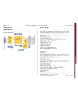
A-GPS Block Diagram:
WLAN (Wi-Fi)
This WLAN module is based on the new Marvell 88W8686 chipset. WLAN module is
designed to support IEEE 802.11a or 802.11g payload data rates of 6, 9, 12, 18, 24, 36,
48 and 54 Mbps, as well as 802.11b data rates of 1, 2, 5.5 and 11 Mbps. For security
the WLAN module supports the IEEE 802.11i security standard through implementation
of the Advanced Encryption Standard (AES)/Counter Mode CBC-MAC Protocol (CCMP),
and Wired Equivalent Privacy (WEP) with Temporal Key Integrity Protocol (TKIP) security
mechanism. For video, voice and multimedia applications the WLAN module supports
802.11e Quality of Service (QoS). The 3-wire Bluetooth / WiFi co-existence interface is
also supported. The WLAN module has a fully integrated RF to baseband transceiver that
operates in both the 2.4 GHz ISM radio band for 802.11g/b WLAN applications and 5
GHz UNII radio band for 802.11a WLAN applications. It contains all the circuitry to
support both transmit and receive operations. The integrated LNA and AGC on the
receive path is seamlessly controlled by baseband functions. Integrated transmitters up-
convert the quadrature baseband signal and the deliver the RF signals to external power
amplifiers for 2.4 GHz and 5 GHz radio band transmission. Local oscillator frequencies
are generated by a fully integrated programmable frequency synthesizer. The loop
bandwith is optimized for phase noise and dynamic performance and quadrature signals
are generated on-chip.
BT/WLAN Co-existence
Standards bodies did not fully anticipate the range of scenarios in which WLAN and
Bluetooth would compete for the same spectrum therefore IEEE 802.11 (WLAN) and
Bluetooth use the same 2.4 GHz ISM frequency band (although they use different access
mechanisms). They also did not include comprehensive, robust, and cooperative
mechanisms in their respective standards to mitigate interference. Since no mechanism
for exchanging signal status information has been built into the two standards, the task
of minimizing interference must be accomplished by other means. Co-location refers to
the situation where both Bluetooth and WLAN are in functional mode, that is, they are
both fully radio operational, performing either transmission or reception activities (or
ready to do so immediately). They also either share an antenna or each module has its
SEMC Troubleshooting Manual
97
(124)

