


en
31
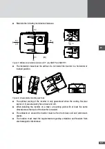
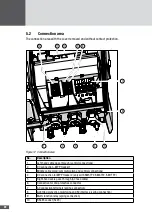
2. Remove the left-hand contact protection as described in Section 5.1.3.
WARNING!
Fatal electric shock hazard!
Cables conducting mains voltage must be covered by the contact protection
inside the inverter.
■
■
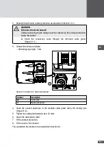
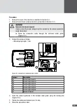
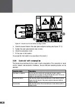
Route the connection cable through the left-hand cable gland
(Figure 21 / 1).
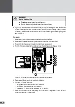
3. Connect the wires as follows:
– Wire stripping length: 7 mm
1
2
Figure 21 Connection of "external shutdown“
Contact
Description
NA
Control line
N
Neutral conductor
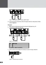
4. Close the unused apertures in the multiple cable gland using the locking pins
(Figure 21/2).
5. Tighten the cable gland (wrench size: 34 mm).
6. Check the cable strain relief.
7. Fit the contact protection.
8. Fit the cover of the inverter.
You can switch the inverter on as described in Section 6.1.


