


4
Contents
1 Notes on the present instruction manual
5
1.1 Scope. . . . . . . . . . . . . . . . . . . . . . . . . . . . . . . . . . . . . . . . . . . . . . . . . . . . . . 5
1.2 Target groups . . . . . . . . . . . . . . . . . . . . . . . . . . . . . . . . . . . . . . . . . . . . . . . . 5
1.3 Storage of the documents . . . . . . . . . . . . . . . . . . . . . . . . . . . . . . . . . . . . . . 6
1.4 Symbols used. . . . . . . . . . . . . . . . . . . . . . . . . . . . . . . . . . . . . . . . . . . . . . . . 6
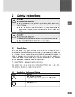
2 Safety instructions
7
2.1 Intended use . . . . . . . . . . . . . . . . . . . . . . . . . . . . . . . . . . . . . . . . . . . . . . . . 7
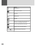
2.2 Symbols at the Compact Station . . . . . . . . . . . . . . . . . . . . . . . . . . . . . . . . . 7
3 Description 9
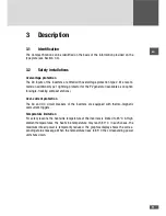
3.1 Identification . . . . . . . . . . . . . . . . . . . . . . . . . . . . . . . . . . . . . . . . . . . . . . . . 9
3.2 Safety installations. . . . . . . . . . . . . . . . . . . . . . . . . . . . . . . . . . . . . . . . . . . . 9
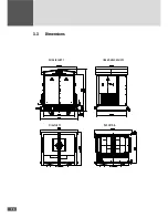
3.3 Dimensions . . . . . . . . . . . . . . . . . . . . . . . . . . . . . . . . . . . . . . . . . . . . . . . . 10
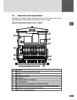
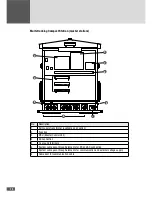
3.4 Connection area Compact Station . . . . . . . . . . . . . . . . . . . . . . . . . . . . . . . .11
3.5 Operating elements at the MCU . . . . . . . . . . . . . . . . . . . . . . . . . . . . . . . . . .13
3.6 Access area to the inverters. . . . . . . . . . . . . . . . . . . . . . . . . . . . . . . . . . . . .14
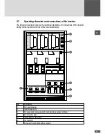
3.7 Operating elements and connections at the inverter. . . . . . . . . . . . . . . . . . .15
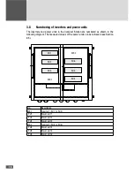
3.8 Numbering of inverters and power units. . . . . . . . . . . . . . . . . . . . . . . . . . . 16
4 Installation 17
4.1 Transporting and storing the Compact Station . . . . . . . . . . . . . . . . . . . . . . .17
4.2 Checking the delivery . . . . . . . . . . . . . . . . . . . . . . . . . . . . . . . . . . . . . . . . . .18
4.3 Selecting the installation location. . . . . . . . . . . . . . . . . . . . . . . . . . . . . . . . .18
4.4 Installing the Compact Station . . . . . . . . . . . . . . . . . . . . . . . . . . . . . . . . . . .19
5 Electrical connection
21
5.1 Installing cable pass-through elements . . . . . . . . . . . . . . . . . . . . . . . . . . . 21
5.2 Connection to PV generator . . . . . . . . . . . . . . . . . . . . . . . . . . . . . . . . . . . . 23
5.2.1 General connection conditions . . . . . . . . . . . . . . . . . . . . . . . . . . . 24
5.2.2 Connection of single-tracking compact stations . . . . . . . . . . . . . . 24
5.2.3 Removing the panels from the Compact Station . . . . . . . . . . . . . . 26
5.2.4 Connection of multi-tracking compact stations . . . . . . . . . . . . . . . 26
5.3 Connection to the medium voltage Compact Station . . . . . . . . . . . . . . . . . 28
5.3.1 Connecting conditions. . . . . . . . . . . . . . . . . . . . . . . . . . . . . . . . . . 28
5.3.2 Procedure . . . . . . . . . . . . . . . . . . . . . . . . . . . . . . . . . . . . . . . . . . . 29
5.4 Grounding the Compact Station . . . . . . . . . . . . . . . . . . . . . . . . . . . . . . . . . 31
5.5 Wiring the MCU interfaces . . . . . . . . . . . . . . . . . . . . . . . . . . . . . . . . . . . . . 32
5.5.1 Cable installation. . . . . . . . . . . . . . . . . . . . . . . . . . . . . . . . . . . . . . 32
5.5.2 Status signaling contact - X411. . . . . . . . . . . . . . . . . . . . . . . . . . . 32
5.5.3 Shutdown 2 - X511 . . . . . . . . . . . . . . . . . . . . . . . . . . . . . . . . . . . . 33
Содержание 330TS-SV Compact Station
Страница 3: ...en 3 en 3...
Страница 12: ...12 3 3 Dimensions Vorderansicht linke Seitenansicht Draufsicht Schnitt A A...
Страница 22: ...22 Installation plan Compact Station 1000 mm Ev 2 50 MN m2 Ev 2 20 MN m2 725 400 75 1 4 3 2 5 7 6...
Страница 27: ...en 27 25 mm M12 3 2 4 6 1 5 No Description 1 NH fuse circuit breaker...
Страница 83: ...en 83 Notes...


