|
67
December 2020
|
Solar Stik
®
, Inc.
System Setup and Operation Manual for the Solar Stik G-BOSS E Light HPS
PRELIMINARY
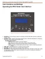
Battery Icon:
Reports battery SOC, voltage, and net current to/from the System battery. The
SOC may be reported as “--” until the System batteries cycle enough to “learn” how to calculate
accurately the SOC. Net battery current is the sum of all chargers and loads connected to the System
batteries. A positive value is net charging; a negative value is net discharging. For example, +30 amps
of charge current and -5 amps of load current will display a net current of +25.0 amps.
Note:
The net negative current will be observed when the Power Hub is the primary power
management device in the System. If the Power Hub is not the primary power management
device in the System, obtain the battery SOC from the primary power management device
instead.
Status Icon
: Reports the time of day and “alarms”. A list of the alarms/notifications that may occur,
their meanings, and their solutions is provided in subsequent sections of the manual.
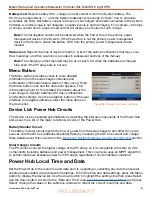
The Menu button provides access to more detailed
information from the solar charge controllers and
notifications (information about alarms if they occur). Push
the Menu button once and the device list appears. This
is the starting point for the detailed information about the
solar chargers, System batteries (DC bus), notifications,
and System settings. Use the navigation buttons of the user
interface to navigate submenus under the menu items on
the device list.
Menu Button
Note:
The charging current reported may be at or near 0.0 A when the batteries are charged
fully, even if the PV arrays are in full sun.
Figure 46. Device list on user interface
Power Hub Local Time and Date
Set the Power Hub to the local time and date prior to operating or collecting any data to ensure all
events are associated with accurate time stamps. To find the time and date settings, press the Menu
button to display the device list. Use the down button to highlight the settings line then press Select.
Use the down button to scroll to the “Date and Time” (see
) and press
Select. Change the values in the submenu windows to reflect the correct local time and date.
Device List: Power Hub Circuits
The Device List is populated automatically by detecting the internal components of the Power Hub
and as such is a list of the major functional circuits of the Power Hub.
Battery Monitor Circuit
The battery monitor circuit reports the flow of power from the solar chargers, and other DC power
sources onto the DC bus (batteries/Expander Paks) by measuring the DC bus current and voltage.
More details about this circuit are in the
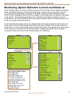
Monitoring System Batteries: Current and Historical
Solar Charger Circuits
The PV controls convert the higher voltage of the PV arrays so it is compatible with other 24 VDC
components including batteries and power management. This circuit also uses an MPPT algorithm
to extract maximum available power from PV arrays regardless of environmental conditions.

