December 2020
|
Solar Stik
®
, Inc.
48
|
System Setup and Operation Manual for the Solar Stik G-BOSS E Light HPS
PRELIMINARY
c Program PRO-Verter to Match AC Source Output Current
Set the “Grid Max Current” setting to the same value as the maximum continuous output current
of the AC grid power source connected to the PRO-Verter. Set “Gen Max Current” value using the
recommended settings in Table 1 below. These settings are required to optimize generator/PRO-
Verter interactions and System performance. If the PRO-Verter current setting is greater than the
power source, the source will be overloaded and fault. If the PRO-Verter current setting is lower
than the power source, System performance will be reduced or not be able to support loads that fall
within the rated performance of the PRO-Verter.
Table 1. AC Power input settings for generators
Recommended generator AC Input Settings and Loads
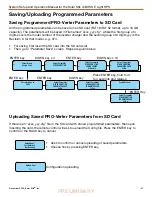
Program AC Input Currents
1
Press ENTER (right arrow) button.
2
Press DOWN button to arrive at Input Setting.
3
Press ENTER button.
4
Press DOWN button to arrive at Grid Max Current.
5
Press ENTER button and hold until number flashes.
6
Use UP or DOWN button to change number.
7
Press ENTER to move to next digit.
8
When correct value is entered, press and hold ENTER to save.
9
Press DOWN button to arrive at Gen Max Current.
10
Repeat steps 5 through 8.
Select Group
CHARGE CURVE
Select Group
INPUT SETTING
EVO-2224
AC output:
Standby
120.0V
<0.1 A
60.00Hz
*
*
Select Parameter
INPUT SETTING
DEFAULT FREQ
0=60Hz
Select Parameter
INPUT SETTING
GRID MAX CURRENT
20.00A
*
*
“INPUT SETTING”
Home Screen
Select Parameter
INPUT SETTING
GEN MAX CURRENT
20.00A
Do not operate with lids open in wet environments.
Keep cables and other equipment dry.
Energy Storage
24VDC PRO-Verter S 3000
24VDC Power Hub 3500
PDM 3000
Power Generation
Power Management
1 kW Defender
MPG
1 kW Defender
MPG
Optional AC Load
Load
Inter-Connect Strip 7
OR
ESMs
ESM (x2)
E
E
B
E
E
E E E
E
A
A
D
D
C
F
Regulated DC
Load-
PDU
H
G
Unregulated DC
Load-
Tower
PV Arrays
PV Arrays
24VDC PRO-Verter S 3000-120 AGS
System Con�guration� Setup� Operation� and Safety Information
Notice
KEEP IT COOL.
Shade the PRO-Verter and Power Hub to reduce solar loading and
subsequent derating of their output.
Clean or replace PRO-Verter and Power Hub air intake �lters regularly to maintain
optimal performance.
Spare �lters may be located behind I-Plates.
HEAT-RELATED DERATING:
Internal temperatures over
122 �F (50 �C) will signi�cantly reduce
the power the PRO-Verter can supply to charge batteries and to buffer surge loads.
DO NOT STORE BATTERIES IN A DISCHARGED STATE!
Always recharge batteries completely
before storage or transport.
DO NOT USE THE PRO-VERTER IN CONJUNCTION WITH A MODIFIED SINE WAVE AC INPUT
SOURCE.
This PRO-Verter is programmed to charge 24 VDC lithium-ion batteries using a constant current/
constant voltage (CC/CV) charging protocol.
Voltage is not an indicator of battery state of charge.
Contact Solar Stik Technical Support if recon�guration to another battery chemistry is required.
A functioning 24 V battery must be connected for the PRO-Verter and Power Hub to operate.
Solar panels, should be oriented for maximum daily sun exposure.
Consult the generator manual for critical generator operation information.
The AGS Tech port is for maintenance only. Contact Solar Stik Technical Support for information.
Quick-start Guide
Connect Hybrid System Components
Refer to diagram and cable legend for recommended setup and connections.
Con�rm System is connected as illustrated in the diagram.
When connecting compatible power generation sources:
Defender/Ranger
Man Portable Generators (MPG) single operation�Connect to GEN
COMM #1 or #2 port.
Defender/Ranger
MPG tandem operation�Connect to GEN COMM #1 and #2 ports. (Use
Parallel Power Cable.)
Tactical Quiet Generator
(TQG; optional)�Connect ONLY to GEN COMM #1 port.
Photovoltaic (PV) Arrays
�Connect to SOLAR ONLY port. Orient arrays to maximize daily
PV power production. Secure PV arrays to ground after all other System Component
locations have been established.
System Activation and Initialization
1. Activate the Hybrid Power System.
a.
.
Turn on energy storage module (ESM) main power switches
b. Turn on PRO-Verter user interface.
2. Set PRO-Verter clock.
a. Press ENTER button.
b. Press DOWN button to arrive at TIME SETTING; press ENTER.
c. Use UP and DOWN buttons to change value of digit.
d. Press ENTER when value is correct to move to next digit.
e. Press ENTER to �nalize setting procedure.
3. Program AC input currents to match power source capacity.
See also Hybrid System Con�guration Chart to the right.
a. Toggle Generator Type switch to desired position.
b. Program AC Input Currents (= generator or grid output(s)).
i. Press ENTER button.
ii. Press DOWN button to arrive at INPUT SETTING.
iii. Press ENTER button.
iv. Press DOWN button to arrive at
GRID MAX CURRENT
.
v. Press ENTER button and hold until number �ashes.
vi. Use UP or DOWN button to change number.
vii. Press ENTER to move to next digit.
viii. When correct value is entered, press and hold ENTER to save.
ix. Press DOWN button to arrive at
GEN MAX CURRENT
.
x. Repeat steps v. through viii.
4. Initiate System cycling.
a. Toggle Generator Control switch(es) to ON position. Once generator has run for two
(2) minutes, AC input should be quali�ed.
b. When PRO-Verter enters Charging mode,
rapidly
toggle Generator Control
switch(es) to AUTO position to allow charging cycle to complete automatically.
PDM 3000: PDU and/or Tower Operation
After the Hybrid Power System is cycling, turn on PDM 3000 breaker(s) to support required
circuit(s) (Tower and/or PDU). Turn off PDM 3000 breaker(s) when circuit(s) not in use.
System Deactivation
Power down PRO-Verter user interface
before
disconnecting batteries. Press and hold user
interface ON/OFF button for �ve (5) seconds, then release. The user interface will turn off.
PRO-Verter S 3000 NATO Connection
The NATO port allows connection of a NATO 24 VDC circuit to the Hybrid System's 24 V bus.
This can be in support a 24 VDC load or to allow charging from an external 24 VDC source.
Regulated 28 VDC (220 W max) Connection on the PRO-Verter
Supports modest loads with regulated DC power. Contact Solar Stik for connector information
and available adapter cables. Do not attempt to power sensors from this connection.
System Con�guration Re�uirements
Operation of a Hybrid System
When operating in a high-ef�ciency HYBRID model, energy from batteries is used to support
the load(s). The total daily power required for the load(s) is generated by a renewable PV array
and/or a fuel-driven generator. The PRO-Verter S 3000 manages all system functions,
ensuring constant power to the load through proper cycling of the batteries and connected
power generation sources.
The PRO-Verter S 3000 uses battery voltage to initiate generator start and stop functions. In a
properly sized System, the batteries and generator should both cycle 1�2 times daily.
�ee �ybrid �ystem �on�guration ��art �or recommended supported loads, generation
requirements, and recommended battery capacities.
Con�guration of a Hybrid System (See System Manual.)
1. Determine the total daily power requirements.
2. Establish the proper battery capacity.
3. Con�gure generator/grid AC and PV recharging.
WARNING
Shock Hazard
I-PLATE PN: 10-1000661 REV A
Generator
Con�guration
Generator
1
Output (W)
AC Input
2
Setting (A)
Max
Recommended
3
Load-Hybrid (W)
Minimum Energy
4
Storage (kWh)
1 x 1 kW
~600
5�7.5
300
3.9
2 x 1 kW
~1200
10�15
600
5.2
1 x 2 kW
~1500
12.5�15
750
4.9
2 x 2 kW
~3000
25�30
1500
9.8
3 kW TQG
~2800
25
1400
9.2
¹ Power output for reliable and ef�cient generator operation
²
Programmable range for AC input MAX current
³
The recommended load for cycling System 1�2 times per day
4
Minimum energy storage requirement for recommended loads
Troubleshooting
Generator Fault/Failure
If one (1) of two (2) generators running in tandem fails:
Restart the generator or
If the generator will not restart immediately, reprogram the PRO-Verter AC input setting to
half the value for two (2) generators in tandem. To reprogram, use the instructions in step
3 of System Activation and Initialization.
System Recovery with Overdischarged Batteries
If batteries are discharged to a �critical-low� level, the System may cease to function.
There are two (2) methods to restore a System with overdischarged batteries:
1. Connect an active 120 VAC power source to the PRO-Verter 120 VAC Generator Input.
Turn off all breakers EXCEPT the 120 VAC GEN INPUT 30 A breaker. Con�rm LED above
GEN INPUT breaker is lit. Toggle and hold System Recovery momentary switch to
activate the recovery circuit; the LED above the switch will light after two (2) minutes.
Continue holding the System Recovery momentary switch while pressing the user
interface ON/OFF button. After the user interface powers up, release the System
Recovery switch and the user interface ON/OFF button. The System will begin charging
the batteries in about four (4) minutes.
2. Connect an active PV array (exposed to sun) to the PRO-Verter. Turn on the PRO-Verter
user interface. The PRO-Verter will begin charging once the PV voltage is 5 volts higher
than the battery voltage. Use either an active generator/grid 120 VAC source or
continuous PV to charge the batteries.
Cable Legend
A
24VDC 12� Inter-Connect Cable (0 AWG
;
P/N 13-1000292 )
B
24VDC 8� Inter-Connect Cable (2 AWG; P/N 13-0000314)
C
120VAC 10� MPG Parallel Power Cable (P/N 13-1000293; includes P/N 13-1000176)
D
10� Generator Comms Cable (P/N 13-1000288)
E
24VDC 5� Inter-Connect to ESM Cable (P/N 13-1000294)
F
Solar Y Cable (P/N
G
AiB2-32-5SS DC Output
H
NATO 24 VDC Output
Hybrid System Con�guration Chart


