background image

Installation of the camera driver

69

"

The 

Device Manager

 dialog box shows the 

Generic 1394 Desktop

Camera

 entry in the 

Imaging devices

 section. The exclamation

mark indicates a device conflict.

2)

Select the 

Generic 1394 Desktop Camera

 entry and click on the 

Up-

date driver

 button in the device manager button bar.

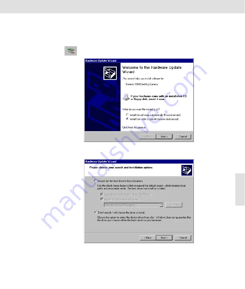
3)

Select the Install from list or specific location (advanced user) and click

on the Next button.

4)

Select the 

Don’t search. I will choose the driver to install.

 option and

click on the 

Next

 button.

Содержание ColorView III

Страница 1: ...analySIS Manual ColorView III ...

Страница 2: ...Soft Imaging System GmbH be liable for any indirect special incidental or consequential damages arising out of purchase or use of this manual or the information contained herein No part of this document may be reproduced or transmitted in any form or by any means electronic or mechanical for any purpose without the prior written permission of Soft Imaging System GmbH Windows Word Excel and Access ...

Страница 3: ...g correction 9 OPERATION OF THE SHADING CORRECTION 10 ACQUIRING CORRECTION IMAGES 11 Enabling Shading Correction 13 Repeat or Update the Reference Acquisitions 13 USE OF THE ONLINE SHADING CORRECTION 14 TECHNICAL NOTE 14 intX and Online Shading Correction 14 Image Acquisition 15 ACQUISITION METHODS 15 Live Acquisition 15 Snapshot 15 intelligent Exposure 15 ACQUISITION 15 CAMERA CONTROL 16 Exposure...

Страница 4: ...dout 22 SNAPSHOT 23 INTELLIGENT EXPOSURE 23 NetCam 27 INSTALLING THE WEB SERVER 28 NETCAM IN THE INTRANET 28 NETCAM IN THE INTERNET 29 USING NETCAM 30 Usage in Black White mode 32 Gamma Correction 32 Display and usage of the acquisition with Real time FFT 32 Camera Set Up 35 SOFTWARE CAMERA CONTROL 35 The Input tab 37 The Display tab 39 The Format tab 43 ...

Страница 5: ... Microscope Settings 45 Appendix II Camera Installation 49 INSTALLATION PROCEDURE WINDOWS 2000 51 INSTALLATION PROCEDURE WINDOWS XP 64 WHEN ENCOUNTERING PROBLEMS WITH THE CAMERA 72 CE DECLARATION OF CONFORMITY 75 ...

Страница 6: ...ColorView III 4 ...

Страница 7: ...ount Its high dynamic scope enables it to acquire images which have very light and very dark areas ColorView III offers the following technical specifications ColorView III Dynamic range 3 x 12 bit using color mode 12 bit using black white mode Exposure times 1 ms to 160 s Frame rates 14 4 s Binning 4 7 3 s Binning 2 3 8 s with full resolution Resolution up to 2576 x 1932 in color mode up to 1288 ...

Страница 8: ... mi croscope The chapter entitled Camera and Light Microscope portrays the elements of the microscope which have the greatest influence on the image quality The correct microscope settings are explained Image Acquisition The chapter entitled Image Acquisition deals with the uses and possibili ties of a digital camera as well as the software required for image acquisi tion This chapter will be the ...

Страница 9: ... which is for the most part uniformly gray or white is selected on the image Such an area must contain an equal intensity of the three color com ponents red green and blue White balance sets the color channels in such a way that the requirements for the selected area are satisfied as much as possible To be able to carry out an effective white balance you need the respective white or gray area Whit...

Страница 10: ...facturer or the graphics card being used 5 Select a color temperature whose color impression best corresponds to that seen in the eyepiece Should your system offer a slide control with the options warm and cold do not alter your color temperature with these Executing White Balance Specialized microscopy techniques It is very difficult to execute a white balance in some microscopic methods i e DIC ...

Страница 11: ...ult Color Settings dialog box is opened 9 Click the Current settings button to adopt the current values for the rest of the work When using this setting the white balance is valid for all images which are acquired with this input channel during the current ses sion 10 Click the OK button to return to the Color Settings dialog box 11 Click the Standard button to save these values as general standar...

Страница 12: ...ons based on these images are done in the camera The image transferred to the PC has already undergone shading correction Dark Images A dark image is an acquisition in which no light falls on the camera Errors can occur from noise or defective pixels which can be corrected by the dark image An own dark image is required for each resolution of the camera Correction Images The illumination of the en...

Страница 13: ...amp voltage as when using normal operation The lamp voltage should not be below 5V Use ND Filters to reduce possible brightness Note ND Filters belong to the basic components of the microscope They will be put into the light path to reduce brightness without altering the color temper ature Should your microscope not have a ND filter or not be able to have one installed you must instead reduce the ...

Страница 14: ...50ms by lowest resolu tion Your online histogram s gray value should be around 2 000 6 Bring the reference sample into the light path and set the Köhler illumi nation The reference sample must be color neutral and have a flat surface devoid of defects or optical structures visible through the micro scope Note Should you not have access to a reference sample you can also use a piece of opaque glass...

Страница 15: ...sure the acquired sample s intensity distribution with the commands in the Measure Intensity Profile submenu Apart from the sample s signature the measured profile is even if the online shading correction is perfectly set Example for an intensity profile without shading cor rection or poorly executed and with shading correction The intensity profile shows a clear decline along the X ax is Alterati...

Страница 16: ...r sav ing the reference images This directory is in the application s working direc tory Its name begins with DGSISFW and continues to contain information about the serial number of the camera being used This directory should not be moved or renamed The reference images file names are also coded in such a way that the on line shading is able to automatically access it Should one or more of the ref...

Страница 17: ...y au tomated image acquisition The automated functions being used coordinate the amplification of the image signals and the exposure time of the acquired image so that a good image result is guaranteed The exposure time of a live acquisition through the resetting of the camera s acquisition mode are kept so short that a very good adjustability during the live image is guaranteed Acquisition Use th...

Страница 18: ...h the camera The Camera Control command and the appropriate dialog box enables you to attain control over numerous setting possibilities required for acquiring single images and live acquisitions The commands in this dialog box are closely interlocked with the settings available from the Image Set Input command Available The Camera Control command is only available if the Set Input dialog box is c...

Страница 19: ...to 20 0 The set value is the factor with which the signal of the corresponding color channel is multiplied Gamma Use the Gamma slide control to obtain a nonlinear contrast enhancement Please note that this gamma filter does not only affect monitor display but also alters actual image information If you are planning on quantitatively evaluating your images at a later time you are advised to use the...

Страница 20: ... way that the color rendering with a specific equipment configuration is ideal for a large scope without any additional changes having to be made Current Settings Click the Current settings button to make the current values be the future standard Sharpen filter Use the sharpen filter to increase the sharpness using edge enhancement already with the live acquisition Sharpen Filter On Off Click the ...

Страница 21: ...ith color cameras due to the fact that this would lead to strong color alterations Use this method with images with weak contrasts or to select a specific signal area fluorescent microscopy Automatic gain display The Automatic gain display method extracts the area to be used based on the actual signals on hand The strongest of these signals will be ignored Use this method with images with a high d...

Страница 22: ...acquisition Manually ad just fixed scal ing Click the Manually adjust fixed scaling button to manually set the upper right hand limit for the fixed scaling The Fixed scaling dialog box is opened Move the Right limit slide control or directly enter the desired numerical val ue into the text box Black balance The black balance is used for background correction The program calcu lates the mean value ...

Страница 23: ...x in which a relative measure ment of the sharpness is displayed by a changing bar which can be varied between Blurred and Focused If you start a live acquisition with an activated Sharpness Monitor or activate it during a live acquisition it will show middle sharpness 50 in each case This is because there is no absolute measurement for the sharpness in an image and because the sharpness monitor o...

Страница 24: ...ings by which the sharpness monitor is at its maxi mum and use these settings for the acquisition Partial Readout The partial readout is a method for fast live acquisition A rectangular part of the image is defined for the partial readout to which the readout is limited during the live acquisition A higher frame rate is attained due to the smaller amount of data to be transferred Available The liv...

Страница 25: ... position and size of the ROI The Set ROI for Partial Readout command does not enable the partial readout you still have to click the Partial Readout On Off button afterwards Snapshot Use the Image Snapshot command acquire a single images and to make it available for the image anal ysis software You may also You can also click the Standard button bar Snapshot button Available The command is not av...

Страница 26: ...rrent in order to make an offset correction possible After successful measurement of the dark cur rent intelligent Exposure asks you to do the next step The second calibration step consists of measuring the signals in various res olution settings This detects the camera s sensitivity A changing live image is displayed in this step You must execute the calibration anew should you change cameras i e...

Страница 27: ...to in crease the live image s frame rate These changes however do not affect the snapshots which were made with intelligent Exposure Snapshot Click the Snapshot button to initiate the acquisition of a snapshot intelligent Exposure acquires an image and saves it to the active image buffer A hint box informing you about the acquisition process appears if the exposure time of a snapshot exceeds one s...

Страница 28: ...ightclick to confirm position and size of the ROI Options Click the Options button to set the options for intelligent Exposure The in telligent Exposure dialog box is opened Dynamic limit in Set the dynamic range in which intelligent Exposure works with the Dynamic limit in slide control Move the controller to the right to increase the dy namic limit This setting results in lighter images with a h...

Страница 29: ...e buffer and a new live acquisition is started in the next image buffer defined in the sequence Keep live after snapshot is only available if you have selected an entry other than None in the Sequence list located in the Special Preferences Image Image acquisition dialog box Calibration Click the Calibration button to begin the camera s calibration process The procedures for calibration are the sa...

Страница 30: ...n the intranet The transfer of images within the company network or intranet generally does not require any further actions Enabling access During installation setup will create a link with the name NetCam html in the Module NetCam subdirectory below the working directory of your image analysis software Send this link via e mail to colleagues you would like to give access to your images The easies...

Страница 31: ... The server s internet address must be entered on the client s page This ad dress is available in the well known alphanumerical form MyComput er OurCompany de and in the numerical form 62 180 61 137 The nu merical form of the address is more reliable especially if your system admin istrator has to alter the network settings Determining the IP ad dress You can find out your computer s IP address fr...

Страница 32: ...ons tab to administer the clients which are to access your images Connected Clients In the Connected Clients list you will see all of the clients which are currently connected with your computer You can mark one of these clients to discon nect the connection to it or to refuse a connection in the future Disconnect Click the Disconnect button to disconnect the connection to the marked cli ent The c...

Страница 33: ... transferred images and thus influence the transfer rate Image quality Use the Image Quality slide control to control the compression of the imag es Move the slide control to the right to maintain a high image quality The data amount of the transferred images increases whereby the transfer rate decreases Move the slide control to the left to increase the compression The image quality decreases whe...

Страница 34: ... Gamma Setting Click the Gamma preferences button to set up a quick gamma correction during a live acquisition The Gamma Setting dialog box is opened Move the Gamma slide control to make a gamma correction of the live im age Move the controller to the left Gamma 1 to make the entire image darker whereby the brightness in light areas will be increased Move the controller to the right Gamma 1 to mak...

Страница 35: ...image The closer such a point is to the center the smaller the spatial fre quency of the correspond ing periodic structure i e the larger the periodic dis tances in the microscope image The cross arises due to fringe effects To achieve optimum on screen display of the fourier image use the RTFFT Control dialog box with the tabs ROI Display and Tools ROI Use the ROI tab to select the region the RTF...

Страница 36: ...ette in the input located on the Display tab Brightness The Brightness slide control enables you to alter the brightness of the Real time FFT display in the RTFFT Display window Move the controller to the right to increase brightness Move the controller to the left to decrease brightness Should you have selected a Display palette the colors will change in the RTFFT Display window Reduced FFT Selec...

Страница 37: ...ical input channels The ColorView software complies with the logical input channel concept This means the camera is as easy to operate as a regular video camera if it is hooked up to the microscope and computer and if the software has been installed and configured No additional menu appears in the user interface s menu bar When you have selected the Set input command located in the Image menu you ...

Страница 38: ...new channel Creating additional input channels Should you want to create additional input channels for example to have dif ferent configurations immediately available for repeating tasks use an al ready existing input channel Duplicate Channels Click the Duplicate Channel button to make a copy of the active input chan nel The new input channel gets the same name as the channel from which it was co...

Страница 39: ...copic reproduction of very dim glowing structures Resolution You can choose three different resolutions possible with ColorView III from the Resolution list The adjustable resolution in ColorView III substitutes bin ning Online shading correc tion You can set the camera function with the same name in the Online Shading correction group Activate Select the Activate check box to use the online shadi...

Страница 40: ... value Values rang ing from 30 to 30 are possible whereby the default value is 10 The image appears smoother when using negative values and sharper when using pos itive values Entering a value of 0 will result in the sharpen filter having no effect at all Convenient alternatives for activating deactivating the sharpen filter as well as for adjusting sharpen filter parameters are the Sharpen Filter...

Страница 41: ... temperature sensors The temperatures are continually measured CCD Chip CCD Chip is the CCD chip s temperature An increase in noise is the result of high temperatures of the CCD Chip The default value for trouble free op eration is 10 C Housing Housing is the temperature of the cameras housing The cameras housing should not exceed 40 C The Display tab Over exposure The Over exposure group enables ...

Страница 42: ...ese Gmin and Gmax gray values in the Left and Right overflow fields this is where you enter the percentage of pixels with the low est gray values which are to be displayed black and which percentage of the highest gray values are to be displayed white This is how you clip gray values that are to be ignored at both the upper and lower ends of the gray value histogram Make use of the overflow values...

Страница 43: ... is equivalent to a gray value of 2174 During a live acquisition you can turn on or off the Automatic Gain Display with the buttons in the online histogram as well as activate and set the fixed scaling Setting the fixed scaling via the online histogram You use the mouse to set the limits of the fixed scaling in the online histo gram Move the pointer over the blue lower limit or red upper limit ver...

Страница 44: ...t the Overscan entry to ensure that all the Viewport s available area will be used The system will select the smallest zoom level 25 50 or 100 where the image fills the whole Viewport In certain cases parts of the im age will not be visible Adjust to viewport Select the Adjust to viewport entry to have the image size adjusted to opti mally fit the Viewport The image will be adjusted to fit the cur...

Страница 45: ...e mode none Select the entry none not to use any palette for the image display Adjust Dither Gamma Mixmap Rainbow So laris Thermal The entries in this list are the names of various lookup tables which can be used for the image display on the monitor The Format tab Active area The display in the Active area field shows how large the acquired image is using the present settings with regards to the l...

Страница 46: ...ction complete clipping If a value for the clipping already has been set the setting possibilities for clipping the opposite edge reduce themselves re spectively Interactive Click the Interactive button to be able to place the clipping interactively into the image document Move the pointer with the mouse button depressed to change the size of the area to be acquired The actual acquired area is mar...

Страница 47: ... out The eyepiece takes on the function of the magnifying glass An additionally important component is the illuminator This illustration clarifies the basic assembly of the com ponents of a microscope in transmitted light mode Illumination Light is a decisive medium for creating images with a microscope As a result the light i e illumination plays an important role in creating the image in the mic...

Страница 48: ...microscopes can insert ND filters into the light path thus reducing the intensity of the lamp s light These ND filters ensure a uniform reduction of light intensity throughout the entire frequency range without altering the col or temperature Köhler Illumination This illumination process which was described by Dr August Köhler as early as 1893 is still an indispensable prerequisite for successful ...

Страница 49: ... into the objective It is based on the refraction index of the lenses being used as well as the objective s angular aperture The manufacturers are narrowly limited when dealing with the refraction index whereas the objective s angu lar aperture can be increased by using appropriate measures To achieve this a fluid with a high refraction index is placed between the cover slip and the objective The ...

Страница 50: ...ColorView III Objective Total Magnification and Useful Magnification 48 ...

Страница 51: ...software on your computer 4 Install the camera and connect it to the computer system What if my computer sys tem already has a FireWire interface If your computer system already has a FireWire interface onboard or a sep arate FireWire board installed you do not need to install the board provided with the camera If you are not sure whether a FireWire interface is available open the Windows Device M...

Страница 52: ...o high temperature or humidity will affect the characteristics of the camera Avoid storage or usage under such conditions Do not subject the camera to too much mechanical shock The FireWire cable plug is not symmetrical You must make sure that the cable plug is facing the same way as the camera socket when you plug the cable into the camera jack Do not disconnect the FireWire cable while the image...

Страница 53: ... hardware configuration or if it is not yet equipped with a FireWire board the FireWire board How to install the FireWire board 1 Turn off the PC and disconnect the power supply 2 Remove the cover from the PC 3 One PCI slot is required for the FireWire board Insert the board into the slot FireWire board installed 4 Replace the cover onto the PC 5 You are now ready to first install the image analys...

Страница 54: ... multiprocessors thus making full use of the power of the latest multi CPU PC s camera driver installation Installation of the SIS View FireWire camera driver is simply done via the image analysis software setup You are only required to select FireWire and specify the additional camera driver during setup Installation of the image analysis software For installation follow the instructions given on...

Страница 55: ...te the precalibration Select the TV adaptor s magnification from the list which has the same name Should you not be working with a remote microscope clear the check box Then mark the checkbox for all mounted objectives in the Magnifica tion of the microscope objectives list Note Should a magnification appear on the microscope objective which does not appear in the list a manual calibration must be...

Страница 56: ...ras via their serial numbers when creating a new logical input channel via Image Set Input New Channel A camera s serial number is located directly below the FireWire jack on the camera housing The camera s serial number is located below the FireWire jack Installation of the camera and cables Don t forget Install the image analysis software first before connecting the camera to the FireWire interf...

Страница 57: ...pe s camera mount Some mi croscopes may require additional optical elements installed between the camera mount and the C mount adapter You may also need to align the orientation of the microscope with that of the stage and also match the focus of the camera image with that of the eyepiece image These settings can be done later when you are able to obtain an image on the screen 5 Plug one end of th...

Страница 58: ... depending on the FireWire board You can use any of them The Digital Signature Not Found MS Windows dialog box es ap pear on your screen Confirm the message as often as neces sary until the dialog boxes disappear 7 Open the Windows Device Manager via Start Settings Control Pan el System Hardware Device Manager The Device Manager dialog box contains the correct SIS FireWire camera driver entry Soft...

Страница 59: ...rrect this by firmly plugging them into the corresponding jack Restart the image analysis software Should the problem still exist continue with the following section What to do when the camera has been con nected before the image analysis software instal lation The error message No SIS View FireWire camera has been found will also appear when starting the program should the camera have been connec...

Страница 60: ... install the correct camera driver from the software s setup CD separately from the software in stallation Do the following 1 Select the Start Settings Control Panel System Hardware Hardware Wizard command 2 Click on the Next button 3 Select the Add Troubleshoot a device option and click on the Next but ton ...

Страница 61: ...Troubleshooting 59 4 Select the entry SoftHard Technology MV 4 0 from the Devices list and click on the Next button 5 Click on the Finish button ...

Страница 62: ...ColorView III Installation Procedure Windows 2000 60 6 Click on the Next button 7 Select the Search for a suitable driver for my device recommended option and click on the Next button ...

Страница 63: ...etup dialog box 9 Make sure that only the CD ROM drives check box is selected and click on the Next button Wait until Windows has found the correct camera driver The driv er s data file is mv40dcam inf You will find it on the CD ROM in Di rectory program support cameras sis_firewire drivers win2k 10 Click on the Next button ...

Страница 64: ...nd dialog box appears on your screen 11 Click Yes Wait until the camera driver has been installed 12 Click on the Finish button The Digital Signature Not Found MS Windows dialog box es ap pear on your screen Confirm the message as often as neces sary until the dialog boxes disappear ...

Страница 65: ... SoftHard Technology MV4 0 Camera The Windows Device Manager shows the IEEE 1394 FireWire board and the SIS View FireWire camera driver Soft Hard Technology MV4 0 Camera 14 Install the image analysis software During the installation check the Firewire check box to in the Input Device Digitizer Selection dialog box Select the ColorView III Firewire check box in the following Cam era Selection dialo...

Страница 66: ...board hardware configuration or if it is not yet equipped with a FireWire board the FireWire board How to install the FireWire board 1 Turn off the PC and disconnect the power supply 2 Remove the cover from the PC 3 One PCI slot is required for the FireWire board Insert the board into the slot FireWire board installed 4 Replace the cover onto the PC 5 You are now ready to first install the image a...

Страница 67: ...PU PC s camera driver installation Installation of the SIS View FireWire camera driver is simply done via the image analysis software setup You are required to select FireWire and specify the additional camera driver during setup Then you have to get Win dows to use the SIS View FireWire camera driver Installation of the image analysis software For installation follow the instructions given on the...

Страница 68: ...re can support several same or different types of FireWire cameras simultaneously You differentiate Color View III cameras via their serial numbers when creating a new logical input channel via Image Set Input New Channel A camera s serial number is located directly below the FireWire jack on the camera housing The camera s serial number is located below the FireWire jack ...

Страница 69: ...scope s camera mount Some mi croscopes may require additional optical elements installed between the camera mount and the C mount adapter You may also need to align the orientation of the microscope with that of the stage and also match the focus of the camera image with that of the eyepiece image These settings can be done later when you are able to obtain an image on the screen 5 Plug one end of...

Страница 70: ...with the camera driver installation before starting the image analysis software Installation of the camera driver The SIS View FireWire camera driver is not signed and therefore not used automatically under Windows XP After having installed the image analysis software and connected the camera to the computer or vice versa you have to go through the following steps to get Windows XP to use the SIS ...

Страница 71: ...amation mark indicates a device conflict 2 Select the Generic 1394 Desktop Camera entry and click on the Up date driver button in the device manager button bar 3 Select the Install from list or specific location advanced user and click on the Next button 4 Select the Don t search I will choose the driver to install option and click on the Next button ...

Страница 72: ...iew III camera selection 5 Click on the Next button The next Hardware Update Wizard dialog box will be opened in the background displaying the message to wait while the Wizard in stalls the software Additionally the Hardware Installation dialog box will pop up in the foreground 6 Click on the Continue Anyway button The Hardware Update Wizard dialog box which had been in the background will become ...

Страница 73: ...on the following dialog box will be opened 7 Click on the Finish button to end the hardware update wizard In the Device Manager dialog box there is still the same Generic 1394 Desktop Camera entry but the exclamation mark indicating the device conflict should have disappeared The camera is now ready for use ...

Страница 74: ...pshots of these messages You can make a snapshot of your active window by using the key combina tions Alt Print respectively Alt Print A copy of the active window is stored to your clipboard and can be easily attached to an e mail using Strg V respectively Ctrl V 4 Since very large e mails can create transmission problems both for the sender and the receiver do not copy screenshots of the entire c...

Страница 75: ...nt way is to use the automatic e mail settings for your customer service query By using the Info System Info Send button an automatic e mail is created which you can then complete and send to us If you have made an example in TIF format please attach this to the e mail as well Be fore sending read the notes in your e mail box the data about your system which you will send to us in this e mail Shou...

Страница 76: ...ColorView III When encountering problems with the camera 74 ...

Страница 77: ...irective of the council on the approximation of the laws of Member States relating to electromagnetic compatibility changed by directive 91 263 ECC 92 31 ECC and 93 68 ECC of the council Compliance was proved by the application of the following electromagnetic compatibility standards EN 55022 1998 A12000 cl B EN 55024 1998 EN 61326 1997 A1 1998 A2 2001 appendix A EN 61000 6 2 2001 EN 61000 6 3 200...

Страница 78: ...76 ...

Страница 79: ...onfigure Input 36 Display tab 39 Format tab 43 Input tab 37 Correction Images 11 D Device ID 39 Device Information 38 Display tab 39 Image scaling 42 Over exposure 39 Palette 43 DLL version ColorView III information 39 Duplicate Channels 36 E Enabling Shading Correction 13 Exposure time Camera Control 16 Input 37 intX 25 Exposure time intX 26 F Firmware Version 39 Fluorescent microscopy 19 Black b...

Страница 80: ... Partial Readout 22 PC Requirements 6 R Real time FFT 41 Requirements PC 6 Resolution Input 37 intX 27 RTFFT Control 33 Display 34 S Select device 36 Serial Number 72 Serial number 39 Set Input 35 Shading Correction Activate 13 Sharpen filter 18 Sharpen filter Activate 38 Sharpness Monitor 21 Snapshot Command 23 intX 25 Special 8 System Info 73 T Tab Format 43 Binning 43 Clipping 44 Image format 4...

Отзывы: