26
Scanner
Connecting to a Vehicle
5.2.1 Cables
One of two data cables, one for OBD-II/EOBD compliant vehicles and an optional one for
non-OBD-II/EOBD models, is used to connect the scan tool to the test vehicle. The 26-pin end of
either cable attaches to the data cable port on the top of the scan tool. The connector is secured
with captive screws. The 16-pin end of the OBD-II/EOBD cable directly plugs into the data link
connector (DLC) of the test vehicle. With the non-OBD-II/EOBD cable, a cable adapter attaches
to the 15-pin end of the cable and the adapter then plugs into the vehicle test connector.
On-screen instructions on the scan tool tell you which cable, and adapter if needed, to use once a
vehicle has been identified. The screen message also includes the location of the vehicle
diagnostic connector the cable attaches to for testing the selected system.
A replaceable 7.5 amp blade-type fuse is installed in the vehicle connector end of the cable to
protect the unit from high circuit voltage and current. A green LED, also on the vehicle connector
end of the cable, illuminates whenever power is supplied to the cable. An LED that fails to
illuminate indicates either a problem on the vehicle power circuit or a blown data cable fuse.
All OBD-II/EOBD vehicles have vehicle battery power (B+) available on the DLC. The optional
auxiliary power cable supplies power for testing non-OBD-II/EOBD models that do not have B+
available on the diagnostic connector. The optional cable and adapters are required for testing
non-OBD-II/EOBD models.
z
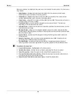
To connect the data cable to the vehicle:
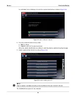
1. Follow the on-screen instructions for connecting to the vehicle (
).
2. Select
Continue
once the data cable is connected.
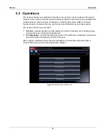
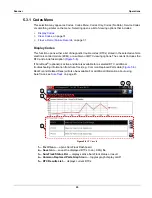
The Scanner establishes communication then displays a list of available tests. If the Scanner
is unable to establish a communications link, a “no communications” message displays.
3. Select from the available tests to open a submenu of test options.
NOTE:
i
The internal battery charger of the diagnostic tool begins recharging the battery any time the data
cable is connected to a powered DLC.
5.2.2 No Communication Message
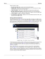
When the screen displays a “no communication” message, it means the scan tool and the vehicle
control module cannot communicate with each other for some reason.
The following conditions cause a “no communication” message to display:
•
The Scanner is unable to establish a communication link with the vehicle.
•
The vehicle is not equipped with the system that was selected.
•
There is a loose connection.
•
There is a blown vehicle fuse.
•
There is a wiring fault on the vehicle.
•
There is a circuit fault in the data cable or adapter.
•
Incorrect vehicle identification was entered.
Refer to the Vehicle Communication Software manuals for manufacturer-specific problems.
Содержание Modis Ultra
Страница 1: ...User Manual EAZ0079L23C Rev B 1 H 18 UK ...


