97
Scope Multimeter
Operation and Controls
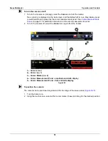
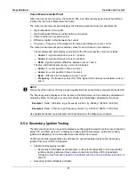
Cursor Measurements Panel
When the cursors are turned on, the Refresh, Min, Live, Max display panel is switched off and
replaced by the Cursor Measurements Panel.
The cursor measurements panel displays the following signal and cursor measurements:
•
Signal amplitude at two points
•
Signal amplitude difference (delta) between two points
•
Cursor position in time at two points
•
Difference (delta) in time between the cursors
•
Frequency - frequency of the signal for the time period between cursor 1 and 2
The cursor measurements panel contains values for each channel in two displays.
The amplitude and delta display is provided in the channel specific color and includes:
–
Cursor 1
- signal amplitude at cursor 1 position
–
Cursor 2
- signal amplitude at cursor 2 position
–
Delta
- signal amplitude difference between cursor 1 and 2
The time and delta display is gray in color and includes:
–
Cursor 1
- cursor position in time at cursor 1
–
Cursor 2
- cursor position in time at cursor 2
–
Delta
- difference in time between cursor 1 and 2
–
Frequency
- the frequency value (Hz) of the signal for the time period between cursor 1
and 2
NOTE:
i
Frequency is the number of times a signal repeats itself per second and is measured in hertz (Hz).
The frequency value displayed, is the inverse of the Delta value, and can also be calculated as 1
divided by Delta. The frequency value (Hz) shown is automatically calculated by the scope.
Example 1
: Delta = 20.46ms, to get frequency divide 1 by .02046 (1/.02046 = 48.87Hz)
Example 2
: Delta = 2.53ms, to get frequency divide 1 by .00253 (1/.00253 = 395.27Hz)
Use applicable decimal point placement during division as the Delta value changes.
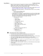
8.5.4 Secondary Ignition Testing
The lab scope function can be used to display secondary ignition waveforms for conventional and
select CIC and COP systems. To display secondary ignition waveforms, optional secondary
ignition coil adapter(s) and a coil adapter lead assembly are required.
Contact your sales representative to purchase the optional adapter leads and/or Secondary
Ignition Clip-on or COP/CIC Adapters.
•
Adapter lead assembly needed:
–
Secondary Coil Adapter Lead Assembly - connects the diagnostic tool to a secondary
ignition adapter (yellow and black scope connectors and black RCA type adapter
connector). See
Secondary Ignition Coil Adapter Lead and Clip-on Adapter (optional)
•
Secondary Ignition Adapters available:
Содержание Modis Ultra
Страница 1: ...User Manual EAZ0079L23C Rev B 1 H 18 UK ...


