


Design / Selection
Warning
1. Do not apply a load in excess of the specification limits.
Select a suitable actuator by work load and allowable lateral
load on the rod end. If a load in excess of the specification
limits is applied to the piston rod, the generation of play in the
piston rod sliding parts, reduced accuracy, etc., may occur
and adversely affect the operation and service life of the
product.
2. Do not use the product in applications where excessive
external force or impact force is applied to it.
Doing so may result in a malfunction.
3. When used as a stopper, select a model with a
stroke of 50 mm or less.
Handling
Caution
1. INP output signal
1) Positioning operation
When the product comes within the set range of the step
data [In position], the INP output signal will turn ON.
Initial value: Set to [0.50] or higher.
2) Pushing operation
When the effective force exceeds the step data [Trigger
LV], the INP output signal will turn ON.
Use the product within the specified range of the [Pushing
force] and [Trigger LV].
a) To ensure that the actuator pushes the workpieces with the
set [Pushing force], it is recommended that the [Trigger LV]
be set to the same value as the [Pushing force].
b) When the [Pushing force] and the [Trigger LV] are set
below the specified range, the INP output signal will
turn ON from the pushing start position.
Handling
2. To conduct a pushing operation, be sure to set the
product to [Pushing operation].
Also, refrain from bumping the workpiece during a positioning
operation or when in the range of the positioning operation.
Failure to do so may result in a malfunction.
3. Use the product within the specified pushing speed
range for the pushing operation.
Failure to do so may result in damage or malfunction.
4. The moving force should be the initial value (100%).
If the moving force is set below the initial value, it may cause
the generation of an alarm.
5. The actual speed of this actuator is affected by the load.
Check the model selection section of the catalog.
6. Do not apply a load, impact, or resistance in addition
to the transferred load during return to origin.
Additional force will cause the displacement of the origin
position since it is based on the detected motor torque.
7. For pushing operations, set the product to a position
at least 2 mm away from a workpiece. (This position
is referred to as the pushing start position.)
The following alarms may be generated and operation may
become unstable if setting is not done correctly.
a. “Posn failed”
The product cannot reach the pushing start position due to
variations in the target positions.
b. “Pushing ALM”
The product is pushed back from the pushing start position
after starting to push.
8. Do not scratch or dent the sliding parts of the piston
rod and guide rod by bumping them or placing
objects on them.
The piston rod and guide rod are manufactured to precise tolerances,
so even a slight deformation may result in a malfunction.
LEG
Series
Specific Product Precautions 1
Be sure to read this before handling the products. Refer to the back cover for safety instructions.
For electric actuator and auto switch precautions, refer to the “Handling Precautions for SMC
Products” and the “Operation Manual” on the SMC website: https://www.smcworld.com
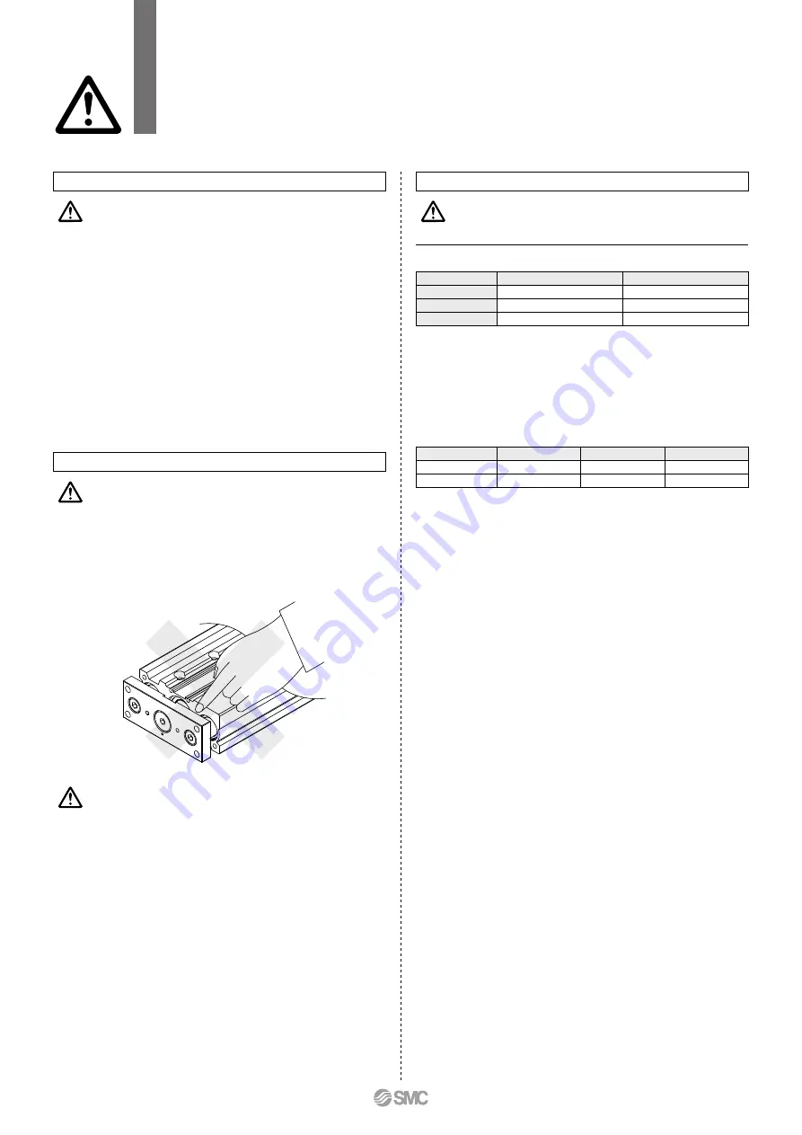
1. Never place your hands or fingers between the plate
and the body.
Be very careful to prevent your hands or fingers from getting
caught in the gap between the plate and the body when
operating.
Warning
Caution
<Set Values for Vertical Upward Transfer Pushing Operations>
For vertical loads (upward), set the pushing force to the max. value shown
below and operate at the work load or less.
There is a limit to the pushing force in relation to the pushing speed. If the
product is operated outside of the range (low pushing force), the completion
signal [INP] may be output before the pushing operation has been completed
(during the moving operation).
If operating with the pushing speed below the min. speed, please check for
operating problems before using the product.
· Battery-less absolute (Step motor 24 VDC)
<Limit Values for Pushing Force and Trigger Level in Relation to Pushing Speed>
Model
Pushing speed [mm/s]
Pushing force (Setting input value)
LEG25M
21 to 35
40 to 50%
LEG32M
24 to 30
50 to 70%
LEG40M
24 to 30
50 to 65%
Model
LEG25
LEG32
LEG40
Work load [kg]
3.6
6.4
11.1
Pushing force
50%
70%
45%
25


