- 24 -
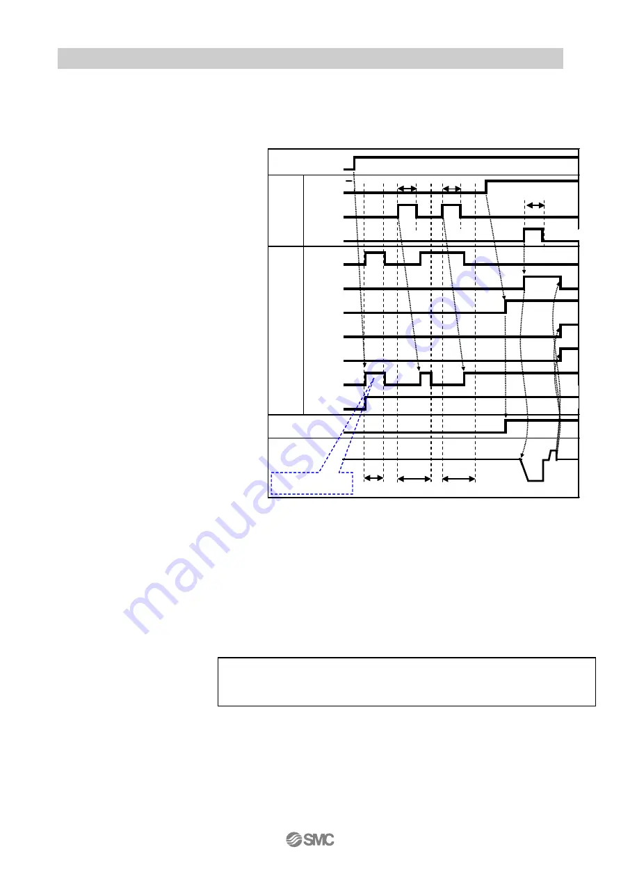
5.3 Operation procedure of parallel I/O
5.3.1 When power is supplied for the first time
(Including when the battery is completely discharged and when the battery is replaced)
- Procedure -
-Timing chart-
1) Supply power
↓
2) *ESTOP output turns on
*ALARM output is turned on once,
then turned off after T1 passed.
([1-153: AbEnc dataALM] is generated)
↓
3) RESET input turns on
↓
4)
*ALARM output turns on once but,
then quickly turns off.
(
「
1-152
:
AbEnc ALM
」
alarm is generated.
「
1-107
:
Low Batt Vol
」
alarm,
「
1-154
:
AbEncCableALM
」
alarm is
generated depending on the case)
↓
5) *ALARM OFF condition is checked
after T3 has passed.
↓
6) RESET input turns on
↓
7) *ALARM turns on
↓
8)SVON input turns on
↓
9) SVRE output turns on
*
The time taken for SVRE output to turn on depends on the actuator type and the operating
conditions.
* Actuator with lock is unlocked.
↓
10) SETUP input turns on
↓
11) BUSY output turns on
(
Starts
)
↓
12) SETON, INP output turns on
Return to origin is completed when BUSY output is turned off
When return to home position is completed.
Afterwards, DRIVE etc. is available.
T1: 1.6s or less (System initialize time + Time required to activate alarm)
T2: 15ms or longer (Recommendation 30ms) (RESET input, SETUP input)
T3: 300ms or less (ALARM inspection time)
SVON
RESET
SETUP
OUT0~3
BUSY
SVRE
SETON
INP
*ALARM
*ESTOP
24V
0V
O
N
OFF
O
N
OFF
0mm/ s
・
・
・
・
・
・
・
・
・
・
・
・
・
T1
T2
T2
T3
T3
T2
* ”*Alarm” and ”*ESTOP” are displayed in negative logic.
* “Power is ON” in the timing chart shows the power supply if ON.
Power
supply
Input
signal
Output
signal
External lock
Release
held
Speed
Controller system is
being initialized
Return to origin
Содержание LECP7-XB54 Series
Страница 19: ...18 motor will be turned OFF...
Страница 24: ...23 Caution When you wish to check the hold of the electric gripper please contact SMC...
Страница 29: ...28...


