manualshive.com logo in svg
background image


Doc. no.IZ

-OMV0005 


1) This product is intended for use in general factory automation equipment. 

Consult SMC before using this product for other intentions. (See Warning No. 4 on page 3) 

2) Use within the specified voltage, temperature and humidity range. 

Operation  with  a  voltage,  temperature  or  humidity  other  than  those  specified  can  cause  malfunction, 

damage to the product, electric shock or fire. 

3)  Use  clean  compressed  air  as  fluid.  (Air  quality  Class  2.6.3  specified  in  ISO  8573-1:    2001  is 

recommended.) 

Never use flammable or explosive gas as fluid. This may lead to fire or explosion. Please contact us when 

fluids other than compressed air are used. 

4) The product is not designed to be explosion proof. 

Never use in an atmosphere of potential dust explosion, flammable gas or explosive gas. It may cause fire. 


1) Clean room specification is not available. 

This  product  has  not  been  cleaned.  When  using  in  a  clean  room  environment,  confirm  the  required 

cleanliness  before  use.  Fine  particles  are  generated  due  to  wear  of  emitters  and  motor  sliding  during 
operation. 


1) Provide adequate space for maintenance, piping and wiring. 

Install the product with consideration for the connector mounting, emitter cartridge assembly for cleaning of 

the emitter, and one-touch fitting for supplying compressed air, so that there is enough space for mounting 
and removal of the power cable, cartridge assembly and air tubing  and for emitter maintenance, inspection 
and wiring. 

To  avoid  applying  unreasonable  stress  to  the  connector  and  one-touch  fitting,  ensure  any  bends  in  the 

cable or air tubing are greater than the minimum bending radius. If the cable or air tubing is bent at an acute 
angle or repeated load is applied to the cable, it may cause malfunction, wire damage or fire. 

2) Mount the product to a flat surface.   

Mounting  on  an  uneven  surface  will  apply  excess  force  to  the  frame  or  case,  which  leads  to  damage or 

failure. Do not drop or apply excessive shock. Otherwise, damage or an accident may occur. 

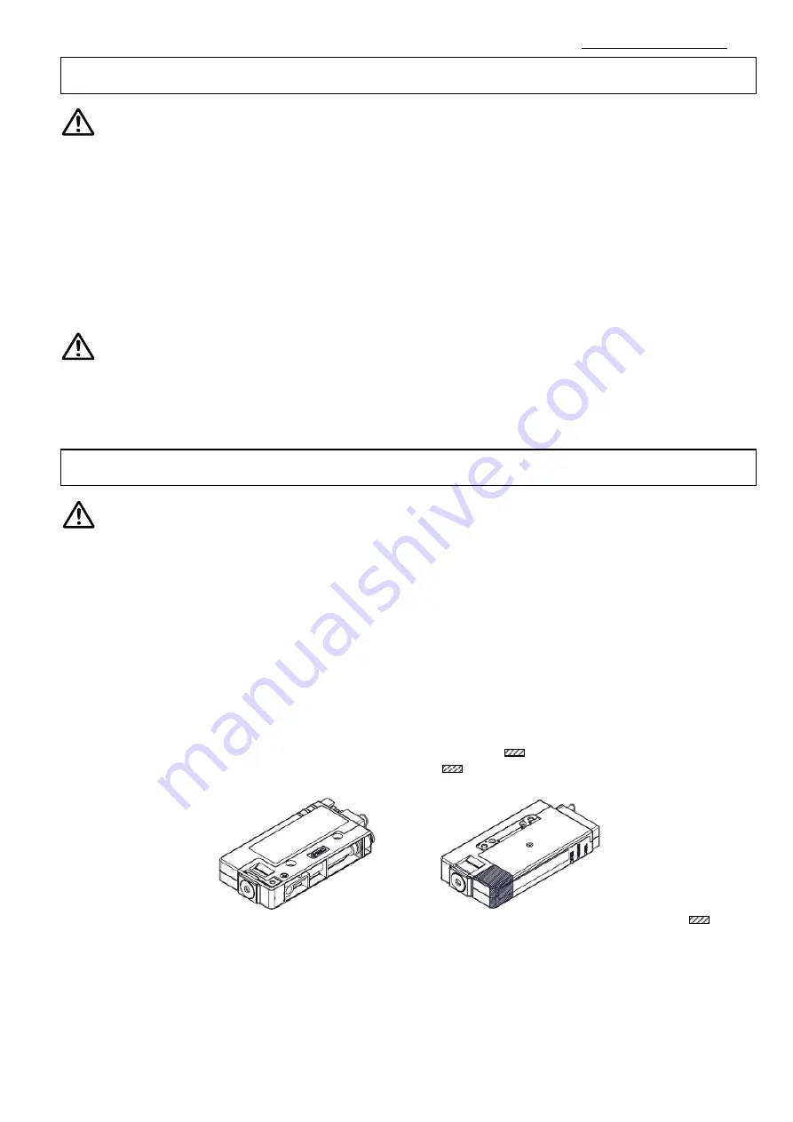
3) Keep the area specified clear when the product is mounted directly on to a base or workpiece which 

are connected to ground.   

Mount the product with the base or work piece avoiding the area (

  shaded) in the drawing below. If the 

grounded  base  or  workpiece  is  too  close  to  the  area  (

  shaded),  ozone  concentration  may  increase 

depending on the operating conditions, causing failure of the product.       


4) Avoid using in a place where noise (electromagnetic wave and surge) is generated. 

If the product is used in an environment where noise is generated, it may lead to deterioration or damage of 

the internal elements. Take measures to prevent noise at its source and avoid power and  signal lines from 
coming into close contact. 

5) Use a correct tightening torque. 

If the screws are tightened in excess of the specified torque range, it may damage the mounting screws, 

mounting brackets, etc. If the tightening torque is insufficient, the mounting screws and brackets may become 
loose. 

Mounting 

Selection 

Refer to page 28 Dimensions for dimensions of the area (          shaded).   


Warning


Caution


Warning 

Содержание IZN10E Series

Страница 1: ...Traffa Schneller Abbau statischer Elektrizit t Bedienungsanleitung D senausf hrung Serie IZN10E...

Страница 2: ...Doc no IZ OMV0005 1 PRODUCT NAME Ionizer Nozzle type MODEL Series IZN10E Series...

Страница 3: ...llation 13 3 1 2 Ionizer Body Installation 14 3 2 Wiring 17 3 2 1 Connection Circuit 17 3 2 2 Wiring of the power supply cable 19 3 2 3 Ground connection 19 3 2 4 AC adapter 19 3 3 Timing chart 20 4 F...

Страница 4: ...equipment failure when configuring the equipment 2 Only personnel with appropriate training should operate machinery and equipment The product specified here may become unsafe if handled incorrectly...

Страница 5: ...e failure of the product 3 Prior to using SMC products please read and understand the warranty terms and disclaimers noted in the specified catalog for the particular products 2 Vacuum pads are exclud...

Страница 6: ...inspection and wiring To avoid applying unreasonable stress to the connector and one touch fitting ensure any bends in the cable or air tubing are greater than the minimum bending radius If the cable...

Страница 7: ...onfirm the effect of the static neutralization after installation 1 Before wiring ensure that the power supply capacity meets the specification and that the voltage is within the specification 2 To ma...

Страница 8: ...se damage to this product These may cause an electric shock fire etc a Areas where ambient temperature exceeds the operating temperature range b Areas where ambient humidity exceeds the operating humi...

Страница 9: ...ized this may cause an electric shock or accident If the cartridge assembly is removed while compressed air is supplied the cartridge assembly will shoot out If cartridges are not securely mounted to...

Страница 10: ...5 to 0 15 MPa Bender tube nozzle IZN10 G X205 0 05 to 0 15 MPa Long nozzle IZN10 G X226 0 05 to 0 15 MPa Fitting Applicable tube O D 6 mm Tube O D 6 mm I D 4 mm Note 1 0 05 to 0 1 MPa Fitting Applicab...

Страница 11: ...cket IZN10E CP Z Symbol Type Nil 3m Z 10m IZN10E CP 01 X13 Symbol Type 01 1m 20 20m IZN10 B1 Symbol Type B1 L bracket B2 Pivoting bracket B3 DIN rail mounting bracket Fixed mounting Pivot mounting Man...

Страница 12: ...w rate nozzle 11 Female threads for piping Rc1 8 Symbol Type 06 6 Metric size 07 6 35 1 4 inch size 16 6 Metric size elbow 17 6 35 1 4 inch size elbow IZN10E Input Output specifications A00 P Symbol T...

Страница 13: ...s the ionizer External input and output cannot be used when the AC adapter is being used 2 Procedures to Operation IZN10E Mounting pitch Mounting stations Symbol Pitch ES 17 4mm Symbol Stations 2 2 st...

Страница 14: ...of the emitter For cleaning or replacing the emitter as shown in drawing step 1 to 3 below remove the power cable and release the cartridge assembly lock by rotating the locking knob to the FREE posit...

Страница 15: ...les When installing the product use M3 hexagon socket head cap screws The screws should be prepared by the user Referring to the figure below affix the product using screws of optimum length M3 screw...

Страница 16: ...holes If the elongated holes are used the flat washers included with the bracket must be used The mounting screws should be prepared by the user Refer to Dimensions section for details Mounting angle...

Страница 17: ...n socket head cap screws M3 x 6 and flat washers included with bracket Refer to Dimensions section for details Tightening torque 0 61 to 0 63 Nm c Fixing to the DIN rail Place the DIN rail in the groo...

Страница 18: ...minal is not grounded the Ionizer will not be able to achieve the optimal offset voltage ion balance Connection circuit NPN Input Output Be sure to ground 24V 24V 24V 24V Power supply 24 VDC 24V 0V F...

Страница 19: ...e Discharge stop signal Pink Reset signal Grey External switch signal 1 Light blue External switch signal 2 White Discharge signal Purple Error signal Yellow Maintenance signal 24V 24V 24V Be sure to...

Страница 20: ...Albeit contact The signal is ON while the product is discharging 6 Purple Error signal OUT Break contact The signal is OFF when the power supply high voltage or CPU is abnormal The signal is ON green...

Страница 21: ...OFF when not normal ON OFF Maintenance signal ON OFF External switch signal 1 ON OFF External switch signal 2 ON OFF Input 24 VDC power supply ON OFF Discharge stop signal Stopped when OFF ON OFF Rese...

Страница 22: ...on it is indicated by the maintenance signal and LED It is recommended to clean the emitters when the maintenance alarm is generated or every two weeks The cleaning frequency varies depending on the e...

Страница 23: ...greater The cleaning kit has a felt pad and a rubber grindstone Choose the felt pad or rubber grindstone depending on the level of contamination to effectively clean the emitters 5 The procedure for m...

Страница 24: ...e arrow Take care with the emitter when pulling the cartridge assembly 4 Hold the emitter assembly which is mounted to the cartridge assembly using tweezers and pull out in the direction of the arrow...

Страница 25: ...ge signal will be turned OFF and the ION HV LED red will be ON to indicate the error When the failure occurs ion generation will be stopped The incorrect electric discharge could be caused by condensa...

Страница 26: ...on an electrified plate dimensions 150 x 150mm electrostatic capacity 20pF defined by ANSI standard ANSI ESD STM3 1 2006 Use this data as a guideline for selection as the performance data may vary de...

Страница 27: ...Doc no IZ OMV0005 26...

Страница 28: ...Doc no IZ OMV0005 27...

Страница 29: ...ergy saving nozzle IZN10E 01 06 07 High flow rate nozzle IZN10E 02 Ground terminal Note Note 2 x M3 x 0 5 depth 10 M3 x 0 5 depth 4 Note Note Dimensions of the area shaded on page 5 Mounting 3 mm A 01...

Страница 30: ...Doc no IZ OMV0005 29 mm Models B C D IZN10E 16 22 16 11 5 IZN10E 17 24 5 18 5 12 Width across flats 12 16 17 One touch fitting Elbow IZN10E Female threads for piping IZN10E 11...

Страница 31: ...ccessory 2 x Hexagon socket head cap screw M3 x 16 Accessory Pivoting bracket IZN10 B2 M o u n t in g a n g le a d ju s t a b le r a n g e M o u n t i n g a n g l e a d j u s t a b l e r a n g e Mount...

Страница 32: ...0005 31 Pivot mounting Inward mounting DIN rail mounting bracket IZN10 B3 Accessory M o u n t in g a n g le a d ju s t a b le r a n g e Mounting angle adjustable range 40o 2 x Hexagon socket head cap...

Страница 33: ...t Output signal IZN10E CG1 Included NPN IZN10E CG1 P Included PNP IZN10E CG2 Not included NPN IZN10E CG2 P Not included PNP 105 Nominal cross section O D Brown Blue Orange Pink White Purple Yellow Gra...

Страница 34: ...directive 2014 30 EC Stainless steel Tungsten Material Weight of the body Weight of the bracket ABS Stainless steel Impact resistance 100m s2 70g 70g 75g 30g Effective static neutralization distance 2...

Страница 35: ...ue to bending chipping or wear of the emitter Examine the emitter tip with a magnifier Replace the emitter referring to 4 3 Replacement of the emitter assembly 10 Green NDL LED is ON 1 Dust or dirt on...

Страница 36: ...a Chiyoda ku Tokyo 101 0021 JAPAN Tel 81 3 5207 8249 Fax 81 3 5298 5362 URL http www smcworld com NOTE Specifications are subject to change without prior notice and any obligation on the part of the m...

Страница 37: ...4 D 91522 Ansbach Tel 49 0 981 48 78 66 50 Fax 49 0 981 48 78 66 55 mail traffa de www traffa de Zentrale TBT Technisches B ro Traffa e K Theodor Heuss Str 8 D 71336 Waiblingen Tel 49 0 71 51 604 24...

Отзывы:

Похожие инструкции для IZN10E Series