HGMS61 Genset Controller User Manual Page 37 of 47
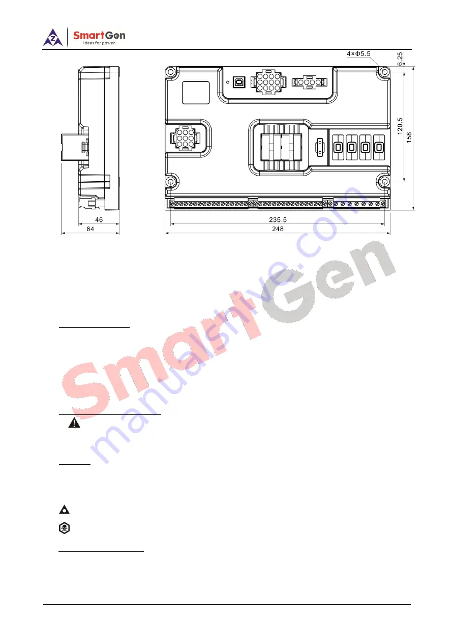
Fig.10 – HGMS61M Case and Overall Dimensions
HGMS61 controller can be applicable to (8~35) VDC battery voltage. Battery negative must be
reliably connected to engine shell. The connection between controller power and battery should
not be less than 2.5mm
2
. If a float charger is fitted, please connect output line of the charger with
battery directly, and then connect battery positive and negative to power input of controller
separately, in case that charger will interfere with the normal running of controller.
1)
Speed Sensor Input
Speed sensor is installed in the engine body for testing flywheel teeth. The connection with
controller uses 2-core shieling line, shield layer should be connected to Terminal16 of controller
and the other end vacant. The other two signal lines are respectively connected to Terminal15 and
Terminal16. At full speed, output voltage range is (1~24)V AC(RMS), 12VAC is recommended
(rated speed). During installing, make the speed sensor contact the flywheel firstly, then pour out
1/3 laps, finally lock nut on the sensor.
2)
Output And Expansion Relay
Caution: All the outputs of controller are relay contact output. If need to expand relay, please
add freewheeling diode in both ends of relay coil (when expansion relay coil links DC), or add RC
loop (when expansion relay coil links AC), in case controller or other equipments are interfered.
3)
AC Input
HGMS61controller must externally connect to current transformer; CT secondary current must
be 5A. Besides, the phase of CT and input voltage must be correct, or the sampling current and
active power may be incorrect.
Notes:
Icom must connect to battery cathode of the controller.
Warning:
When there is load current, open circuit is inhibited in the CT secondary side.
5)
Dielectric Strength Test
When the controller has been installed in the control panel, during the test please disconnect
all the terminals, in case high voltage damages the controller.


