75
4. Screw the bottom half of the slip-ring to the shaft with the two Phillips screws. Ensure the wires
exiting through the center of the shaft are not trapped.
5. Connect the extension reeling drum cable to TB2 on the arm of the slip-ring. The braided shield
connects to the slip-ring TB2 black wire and the center of the cable connects to the slip-ring TB2
brown wire.
6. Secure the extension reeling drum cable to the arm of the slip-ring with two cable ties.
7. Ensure the slip-ring is plugged in all the way.
8. Replace the reeling drum cover.
3.7.8.3
Sensor Baseplate Assembly
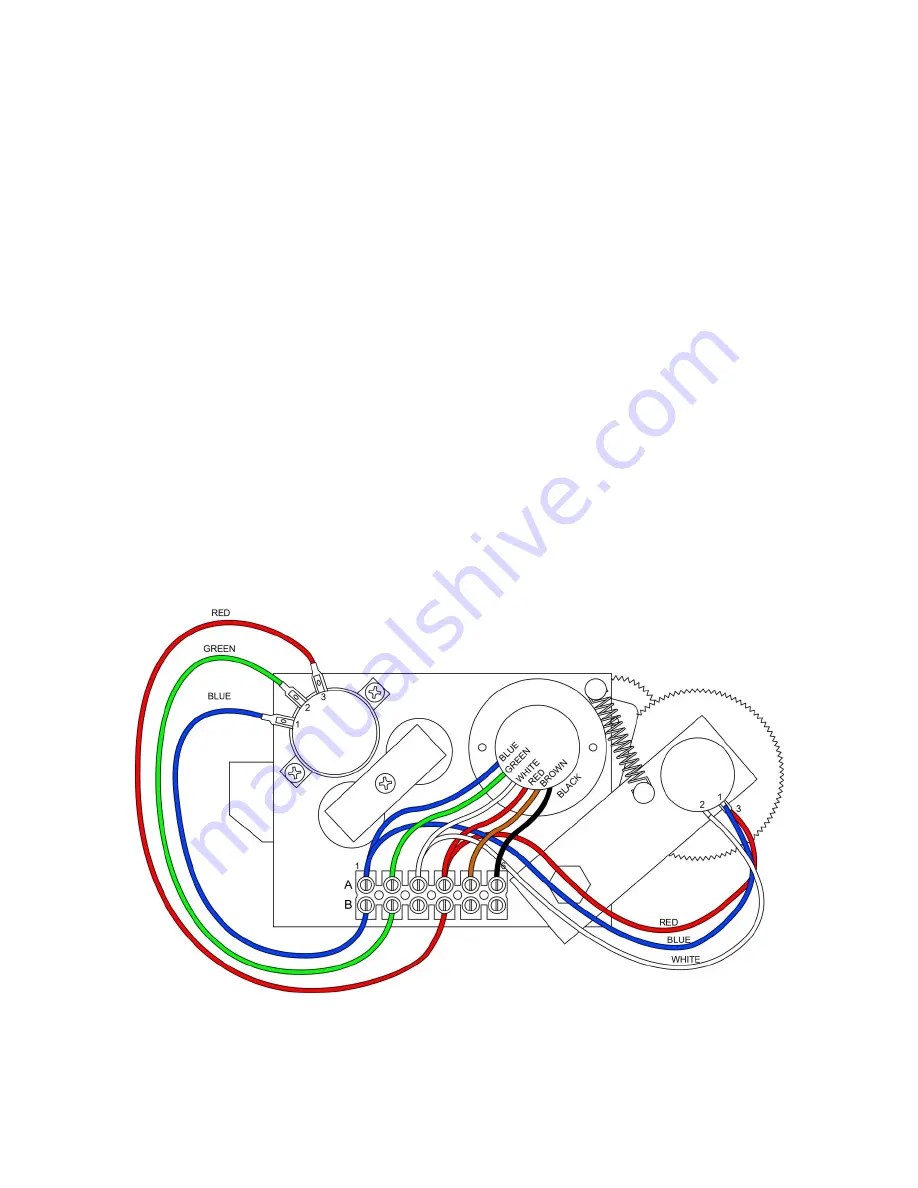
The SENSOR BASEPLATE ASSEMBLY supports both the extension and angle sensors and connects
the sensors, the Anti-Two-Block switch signal to the slip-ring, and the signal cable to the system
computer.
Electrical or mechanical failure of either the angle sensor or the extension sensor potentiometers may
not be field-repaired. The angle sensor pendulum is factory set on the potentiometer shaft, and the
extension potentiometer gear contains a protection clutch which is difficult to replace in the field. If
either of these items fail, replace the whole sensor baseplate assembly.
The terminal block (TB1) provides wiring connection for all internal parts of the reeling drum and the
signal cable connecting the reel to the system computer. Electrical diagnoses of the boom sensors may
be made at this terminal block.
SkyAzúl, Equipment Solutions
www.skyazul.com
301-371-6126
Содержание Greer MG514
Страница 1: ...Greer MG514 Retrofit Installation Calibration and Service Manual...
Страница 2: ......
Страница 4: ......
Страница 88: ......
Страница 89: ......


