74
3.7.8.2
Slip-Ring Assembly
The main purpose of the SLIP-RING ASSEMBLY is to provide an electrical path for the feed and switch
signal return, between the Two-Block switch and the system computer. If replacement becomes
necessary, replace the upper and lower halves of the slip-ring assembly at the same time. Failure of the
slip-ring assembly will most likely result in a continuous Anti-Two-Block alarm. For information on
testing and checking the slip-ring assembly, refer to SECTION 3.9 ANTI TWO-BLOCK FUNCTION
OVERVIEW.
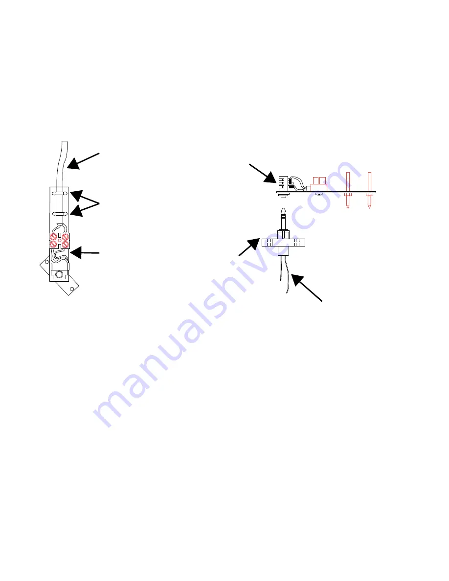
FIGURE 3.7.8.2 - SLIP-RING ASSEMBLY
Removing the Slip-Ring Assembly
1. Remove the reeling drum cover.
2. Hold the reeling drum cable on the arm of the slip-ring and cut the tie wraps.
3. Unscrew the reeling drum cable from TB2 on the arm of the slip-ring.
4. Unscrew both Phillips screws that hold the lower half of the slip-ring on the shaft and remove
the slip-ring.
5. Disconnect the two wires connecting the lower half of the slip-ring assembly at TB1-5 and TB1-6
on the sensor baseplate assembly.
Installing the Slip-Ring Assembly
1. The new SLIP-RING ASSEMBLY is pre-lubricated with grease. Do not wipe off lubrication.
2. Attach the brown slip-ring wire from the lower half of the new slip-ring to TB1-5 on the sensor
baseplate assembly. Ensure the brown signal wire is also correctly connected.
3. Attach the black (or white) slip-ring wire from the lower half of the new slip-ring to TB1-6 on the
sensor baseplate assembly. Ensure the black signal cable wire is also correctly connected.
Wires connect to TB1-5
and TB1-6 on Sensor
Baseplate Assembly
Lower Half mounts to
the end of the Reeling
Drum Shaft
Upper Half plugs
into and rotates on
Lower Half
Reeling Drum Cable
Cable Ties
Slip-Ring Arm
SkyAzúl, Equipment Solutions
www.skyazul.com
301-371-6126
Содержание Greer MG514
Страница 1: ...Greer MG514 Retrofit Installation Calibration and Service Manual...
Страница 2: ......
Страница 4: ......
Страница 88: ......
Страница 89: ......


