background image

SL 30/35 HULL SONAR OPERATORS MANUAL

974-25007001

Issue 2.0

September 2003

Содержание SL 30

Страница 1: ...SL 30 35 HULL SONAR OPERATORS MANUAL 974 25007001 Issue 2 0 September 2003...

Страница 2: ......

Страница 3: ...mrad Mesotech Ltd Is not responsible Underwater Equipment Warranty for Underwater Equipment that is hull mounted such as those mentioned below will be assessed on a case by case basis but shall genera...

Страница 4: ...roducts equipment and or module parts is the responsibility of the servicing agent or dealer All customs duties brokerage charges and local taxes overtime expenses for meals tools launch services ferr...

Страница 5: ...nada LIST OF CONTENTS Part 1 System Familiarization Part 2 System Description Part 3 Control Panel Operation and Display Modes Part 4 Menu and Software Description Part 5 Selecting Settings Part 6 SL...

Страница 6: ...974 25007001 2 0 SL 30 35 Hull Sonar Operators Manual Page 4 List of Contents Kongsberg Simrad Mesotech Ltd Port Coquitlam BC Canada...

Страница 7: ...sue No Date Initial Comments 1 0 05 02 L F First Release 2 0 09 03 L F Second Release To assist us in making improvements to the product and this document Kongsberg Simrad Mesotech welcomes comments a...

Страница 8: ...974 25007001 2 0 SL 30 35 Hull Sonar Operators Manual Page 6 List of Contents Kongsberg Simrad Mesotech Ltd Port Coquitlam BC Canada...

Страница 9: ...Port Coquitlam BC Canada PART 1 SYSTEM FAMILIARIZATION 1 SYSTEM FAMILIARIZATION 1 3 1 1 OVERVIEW 1 3 1 1 1 Equipment Configuration 1 3 1 1 2 System Diagram 1 4 1 1 3 Display 1 5 1 1 4 Processor Unit...

Страница 10: ...974 25007001 2 0 SL 30 35 Hull Sonar Operators Manual Page 1 2 System Familiarization Kongsberg Simrad Mesotech Ltd Port Coquitlam BC Canada...

Страница 11: ...zontal and Vertical Planes are presented The sonar beam can be horizontally trained 360 and 180 in the Vertical Plane The automatic search features and full 90 tilt capability ensure maximum control d...

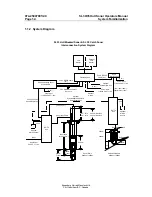
Страница 12: ...Input Power 24 VDC 10 2 5m 4 5m 5 1m Com 1 RS232 Cable 2m Optional External Nav Unit Power input 110 220 VAC 10 2 5m PS 2 KBD Mouse Cables 2m each Speaker Option Optional Synchronisation Cable for Cat...

Страница 13: ...ystem The rear panel of the processing unit contains the connectors for AC and DC power Monitor port two RS232 Serial Ports Keyboard Mouse Printer Network LAN and USB port The Network LAN port can be...

Страница 14: ...p The optional motion sensor for the electronic stabilization of the sonar beams is also located in the sonar room A 10 meters interconnection cable is supplied WARNING If the sonar dome hits a large...

Страница 15: ...s Detection Range 750m for 90kHz 450m for the 160kHz Dome Tilt Upward From 0 to 10 Downward From 0 to 90 Stabilization Pitch and Roll 30 Operating Panel Flush Mounted Integrated Interface Unit Power i...

Страница 16: ...974 25007001 2 0 SL 30 35 Hull Sonar Operators Manual Page 1 8 System Familiarization Kongsberg Simrad Mesotech Ltd Port Coquitlam BC Canada...

Страница 17: ...Wheelhouse Units Description 2 4 2 1 4 1 Display Monitor 2 4 2 1 4 2 Processor Unit 2 4 2 1 4 3 Control Panel 2 5 2 1 4 4 Interface Unit 2 5 2 1 4 5 Interconnect Cables 2 5 2 1 5 Sonar Room Units Des...

Страница 18: ...974 25007001 2 0 SL 30 35 Hull Sonar Operators Manual Page 2 2 System Description Kongsberg Simrad Mesotech Ltd Port Coquitlam BC Canada...

Страница 19: ...he start of the sound pulse projected through water to the reception of the sound pulse reflected back to the sonar transducer The measured time is then converted to distance by using the speed of sou...

Страница 20: ...Monitor The display monitor required for the SL 30 35 can be either a VGA CRT type or any commercial LCD monitor In order to have the full benefit of high resolution we recommend that you select the...

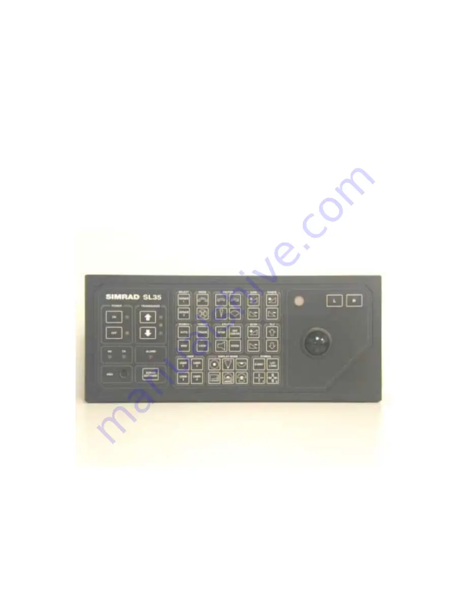
Страница 21: ...lower the intensity of the back illumination An external PC keyboard connector is also provided for use during software maintenance or upgrading The SL 30 35 Control Panel is designed for durability...

Страница 22: ...he fitting of 2 clevis pins and connection of the power cable from the Transceiver Unit The travel length is available in two sizes 250 millimeters and 400 millimeters depending on the installation re...

Страница 23: ...Audio Warning Speaker The Audio Warning Speaker is built into the Processor Unit If you require an external audio speaker You may purchase it locally The audio speaker connects to the rear of the Pro...

Страница 24: ...sberg Simrad Mesotech Ltd disclaims any responsibility for damage or injury cause by improper installation use or maintenance of the product 2 1 9 Copyright The information contained within this docum...

Страница 25: ...or Control Buttons 3 9 3 3 10 1 Move Sector Left Button 3 10 3 3 10 2 Move Sector Right Button 3 10 3 3 10 3 Narrow Sector Button 3 10 3 3 10 4 Widen Sector Button 3 10 3 3 11 Sector Aiming Mode Butto...

Страница 26: ...17 4 Sounder Mode Button 3 19 3 3 17 5 Horizontal Mode with History Mode button 3 19 3 3 17 6 Horizontal Mode with Real Time Vertical Strata Mode Button 3 19 3 3 18 RX and TX Indicator LED 3 20 3 3 1...

Страница 27: ...NEL A thorough understanding of the system functions and controls is necessary to optimize the overall performance Sonar conditions vary sometimes drastically and it is not possible to identify proper...

Страница 28: ...wer ON button for approximately two seconds to power up the sonar The adjacent green LED will light up and remain illuminated indicating that power has been supplied to the sonar and the system is rea...

Страница 29: ...ts down position The middle yellow LED will blink while the sonar dome is lowering The lower green LED will light and remain illuminated when the sonar dome has reached the full down position When the...

Страница 30: ...em by means of the menu system and Tool Bar system on the display 3 3 5 Sonar Selection Buttons You do not need to use the Sonar Selection buttons if you only have one sonar hull unit These buttons ar...

Страница 31: ...s the Range or buttons to increase or decrease the operating range of the sonar Note You also can control the sonar range by using the roller ball and moving the mouse cursor over the display window c...

Страница 32: ...operation 3 3 8 Scan Buttons The Scan Buttons control the Horizontal and the Vertical scanning speed of the selected sonar Use the roller ball to move the mouse cursor over the sonar display you want...

Страница 33: ...rd Negative tilt from 0 degrees to 90 degrees downward You also can control the sonar transducer tilt angle by using the roller ball to move the mouse cursor over the display window control panel tilt...

Страница 34: ...ress the Move Sector Right button to re center the scanning sector Train heading more to the right 3 3 10 3 Narrow Sector Button Press the Narrow Sector button to reduce the width of the scanned secto...

Страница 35: ...ode double arrow button to reverse the scan train direction same as Scan Reverse mode Press the Mode four quadrant button to change the sector train heading by 90 degrees Press the four quadrant butto...

Страница 36: ...ll be displayed on the screen Move the mouse red marker cursor to the position that you want to extend the view and left click the mouse button the range will be doubled in that direction Press the Of...

Страница 37: ...io monitor of fish and or bottom detection This option is used as an audio alert to inform the operator that detection has been made 3 3 13 Target Track and Lock Buttons Press the Target Track button...

Страница 38: ...erent colour Note The Target Track and Lock option are not available at this time on the SL 35 Sonar and will be available in the near future 3 3 14 Auto and Manual Search Buttons Press the Auto Searc...

Страница 39: ...cation on the sonar image then press the LAT LONG button to display a Lat Long marker with a window indicating the latitude and longitude of the selected target Press the LAT LONG button a second time...

Страница 40: ...n on the image Press the Cursor 1 button to automatically display the Cursor Gauge Window and the Cursor 1 marker Use the same procedure with the Cursor 2 button to place the Cursor 2 marker To move C...

Страница 41: ...control panel which contains four operator selectable set ups Frequently used tasks specific to a particular phase of the fishing operation can be pre set in the User 1 2 3 or 4 For example User 1 may...

Страница 42: ...isplay Mode button to provide a sector up plane coverage of 180 degrees with the center of origin at the bottom of the screen You can change the scanned sector width by using the Sector Width button S...

Страница 43: ...or to observe the history of fish movement and distribution equivalent to approximately four full 360 degrees scans It is also useful for detecting bottom fish and reefs Note The History Window cannot...

Страница 44: ...LEDs are provided to indicate that communication is functioning between the Processing Unit and the Transceiver Unit If the LEDs do not blink a communication problem has occurred 3 3 19 Alarm Indicato...

Страница 45: ...is provided to automatically increase or decrease brightness of the light and to turn it off completely in daylight 3 3 22 Menu Description The SL 30 35 Menu Description and Operation is described in...

Страница 46: ...974 25007001 2 0 SL 30 35 Hull Sonar Operators Manual Page 3 22 Control Panel Kongsberg Simrad Mesotech Ltd Port Coquitlam BC Canada...

Страница 47: ...F THUMB 4 12 4 15HOW TO RESET TO THE FACTORY DEFAULT SETTINGS 4 13 4 16HOW TO USE THE BASIC SONAR CONTROLS 4 13 4 17HOW TO SELECT UNITS OF MEASURE FEET YARDS METERS 4 14 4 18HOW TO SET OR ESTIMATE THE...

Страница 48: ...P FOR AND DISPLAY GPS DATA 4 26 4 36 1 To setup the system to accept position data from a GPS receiver 4 26 4 36 2 To setup the system to display position data from a GPS receiver 4 26 4 37HOW TO SETU...

Страница 49: ...gs TVG 4 57 4 59 7 Machine Name Dialog Box 4 59 4 59 8 Parameters Dialog Box 4 59 4 59 8 1 Parameters Magnetic Variation 4 60 4 59 8 2 Parameters Sound Velocity 4 60 4 59 8 3 Parameters Units of Measu...

Страница 50: ...BC Canada 4 59 22 2 Sensors Ports Configuration 4 77 4 59 22 3 User Defined Sensors 4 77 4 59 22 4 Sensors Data Display Box 4 79 4 59 23 System Configuration Dialog Box 4 79 4 59 24 System Message Lo...

Страница 51: ...h as DGPS 4 2 ASSUMPTIONS This manual was written with the assumption that you are already reasonably familiar with Windows operating system If not you should spend a couple of hours with the Introduc...

Страница 52: ...KEY The SL 30 35 uses a software protection system that requires a hardware security key or dongle to be connected to the processing unit printer port to enable full operation of the system If you ar...

Страница 53: ...Port Coquitlam BC Canada 4 6 MAIN CONTROL PANEL Head numbers indicate as well as select the active sonar head in multiple head configuration All other heads are still running in the background but th...

Страница 54: ...den or put into Autohide mode through the View Control Panel menu 4 7 THE TOOLBARS A Toolbar allows you to perform certain operations with a single mouse click instead of the two or more clicks that a...

Страница 55: ...k Data Begin Playback Max Playback Speed Operations Playback Data Max Speed Pause Operations Playback Data Pause Playback Start End Record Data Operations Start End Record Scan Reverse Operations Scan...

Страница 56: ...Scan Horiz with History Operations Control Head Scan 4 9 MARKER TOOLBAR Button Action Menu Equivalent Select Marker 1 None Select Marker 2 None Select Marker 3 None Select Marker 4 None 4 10 THE STATU...

Страница 57: ...rgets Menu are two cross hair type markers that can be placed anywhere on the sonar image to mark a point of interest The Cursors Gauge Window shows their position relative to each other and to the so...

Страница 58: ...ntrol box then reboot the computer In a few seconds the head should be detected and the System Configuration Devices page should change to show the Head Name Part Number and Serial Number You can chan...

Страница 59: ...to the shortest setting that allows you to see what you need to see This will give you the highest update rate and the best image quality See Control Panel Always keep in mind the overall geometry of...

Страница 60: ...Units of Measure dialog box Click a radio button in the Distance group to select the distance units you want to use Click a radio button in the Temperature group to select the temperature units you w...

Страница 61: ...salt water will be somewhere in between Click the Calculate button The calculated value will be entered automatically in the Value to be Used box Click the OK button 4 19 HOW TO INTERPRET THE SONAR IM...

Страница 62: ...the known height of the sonar ahead 4 19 5 Noise and Interference It is usually easy to recognize interference from other acoustic sources such as echo sounders pingers or other sonars These sources...

Страница 63: ...one wall to another and finally back to the sonar transducer The sound path is similar to the path of a billiard ball making multiple bounces off the sides and ends of the table Although it is not ve...

Страница 64: ...erent user names This allows multiple users to save and quickly recover their preferred settings 4 22 1 To create a new user name and configuration Select Users in the Configuration menu then select D...

Страница 65: ...make a customized version of this box you must make a duplicate and then modify it To make a customized head settings display window Right click anywhere in the sonar window to open the popup menu Se...

Страница 66: ...Label in the Used Parameters list then pressing the Remove button Click the Close button the new gauge window will appear in the upper left corner of the sonar window and can be dragged to any desired...

Страница 67: ...enerated by a remote machine in server mode Passive clients can not be operating sonar heads locally The passive mode prevents the user from controlling the remote sonar heads Display settings such as...

Страница 68: ...omcnfg and press OK to open the Distribute Com Configuration Properties dialog box Click on the Default Properties tab to open the Distributed COM Configuration Properties Default Properties page Chec...

Страница 69: ...rties dialog box Press OK to accept and close this dialog box Reboot the computer to make the changes take effect 4 30 HOW TO SETUP THIS SONAR AS THE SERVER To setup this sonar as the server In the Ne...

Страница 70: ...enu select Request Control Note 1 The system must be enabled for a network connection before using this feature See How to Setup a Network Connection Windows XP Note 2 The active client can control an...

Страница 71: ...rces you want to record Click the OK button data from the selected sources will be written to the selected file as it is received from the sensors 4 35 HOW TO EXPORT DATA TO A SERIAL PORT The data exp...

Страница 72: ...e Connect button below this list An icon for the GGA sentence will appear under the selected COM port icon Note You can also use GGL RMA or RMC if your GPS does not support the GGA sentence Click the...

Страница 73: ...tab to open the Sensors Ports Configuration page Click on the COM port icon that you are using for the compass Click the Use NMEA Settings button Note This will set the Bits Per Second Baud rate to 48...

Страница 74: ...tup the system to accept data from a user defined sensor Select Sensors in the Configuration Menu to open the Sensors Configuration Sensors Selection page Click on the User Defined Sensors tab Create...

Страница 75: ...ta as above In the View menu select Sensors 4 40 THE FILE MENU The File Menu contains the following items Save Image is used to save the image in the active window as a bitmap file Save Without Overla...

Страница 76: ...ge to use the entire display area Screen Fit Image allows the sonar image to be enlarged or shrunk to the current dimensions of the display window This feature requires considerable computing time and...

Страница 77: ...rsors opens the Cursors Gauge Window Head Settings opens the Head Settings Gauge Window Magnifier opens the Magnifier Window High Resolution sets the sonar to use a high resolution 1280 by 1024 displa...

Страница 78: ...r the current user It is advisable to save the settings after you have setup the system as desired so that a copy of the settings is immediately saved in the registry and available the next time you r...

Страница 79: ...Dialog Box 4 47 THE OPERATIONS MENU The Operations Menu contains commands required for everyday operation of the sonar Run Sonar Heads causes the detected heads to start operating Note You will see th...

Страница 80: ...rding Export opens the Export Dialog Box allowing you to export data Pause Export pauses the exporting of data on a serial port End Export ends the exporting of data on a serial port Playback Data ope...

Страница 81: ...and press the left mouse button Once placed the cursor overlay can be dragged with the Arrow Tool Reference Cursor 2 Identical to the Reference Cursor 1 Tool except that it refers to the secondary re...

Страница 82: ...ton for calculations to start A measurement overlay is then placed on the display and you must click once when you are satisfied with its location Area and perimeter information will be displayed in t...

Страница 83: ...client machine There can be multiple clients attached to a server machine The system prompts the user with the Client List dialog box to select a particular machine Beep Remote This is a diagnostic pr...

Страница 84: ...e becomes the active controller Both clients are informed of the change in the active client Relinquish Control An active client may become passive through the use of this menu Remove Control Privileg...

Страница 85: ...ntally arranges all of the open windows as horizontal tiles Tile Vertically arranges all of the open windows as vertical tiles Arrange Icons allows you to arrange all icons 4 52 THE HELP MENU The Help...

Страница 86: ...y Settings dialog box associated with this view to change colors Select Control Head to open the Head Settings Dialog Box Select Clear Display to clear the sonar image from the screen Customize opens...

Страница 87: ...ws with completely user configurable set of parameter list through the customized gauge window 4 55 ABOUT DIALOG BOX The version number is the software version of the SL30 35 sonar installed on your c...

Страница 88: ...enu and Software Description Kongsberg Simrad Mesotech Ltd Port Coquitlam BC Canada If the Dongle is programmed to operate a server machine it will display the Server option enabled message 4 56 ADD U...

Страница 89: ...nintentionally If you select Yes and there is network connections then the system will ask you to confirm disconnecting from the remote machine If there are no network connection or you select Yes to...

Страница 90: ...u select Yes you will get another dialog where you can specify to which user you want to save these settings 4 59 DISPLAY SETTINGS DIALOG BOX The Display Settings dialog box allows you to set display...

Страница 91: ...SL 30 35 Hull Sonar Operators Manual 974 25007001 2 0 Menu and Software Description Page 4 45 Kongsberg Simrad Mesotech Ltd Port Coquitlam BC Canada...

Страница 92: ...elements in the display for each view When in Fused Head display these colors are associated with the first head which is the head whose name appears first on the view title The Colors On Second Head...

Страница 93: ...The Rx gain type is used to enable elementary image processing for reverberation control RCG automatic gain control AGC or a combination of the two The Rx Gain Response is the severity of the gain co...

Страница 94: ...the same control as that provided by the Control Panel with the exception that this control is accessible during the playback mode 4 59 3 Distributed COM Configuration Properties Applications See HEL...

Страница 95: ...o enable export of data to an available COM port Select the port to use in the combo box In the Select Sources area select a COM port or a head from which you want to export the data Individual sensor...

Страница 96: ...Page 4 50 Menu and Software Description Kongsberg Simrad Mesotech Ltd Port Coquitlam BC Canada 4 59 5 4 Export Ports Configuration The Export Ports Configuration page allows you to configure the commu...

Страница 97: ...e set exactly the same as on the system to which you will be exporting data You can click on the Use NMEA Settings button to set all of the above settings to the standard settings used for NMEA device...

Страница 98: ...ides a 360 degree plane of coverage for general search Bow Up Provides a sector up plane of coverage of 180 degrees with the center at the bottom of the screen You can change the scanned sector width...

Страница 99: ...idth of the sector Use the slider controls or the increase decrease buttons for either adjustment The area to be scanned is shown graphically above these controls Tilt controls allow you to control th...

Страница 100: ...ormance The option can usually be set to On due to negligible effect of the loss in color depth The Pulse Length control can be used to set the desired transmit pulse length on heads that support this...

Страница 101: ...ated test tone for factory testing For the new 1071 based analog sonar heads the Test tone is automatically selected if the transmitter is turned off in low Power mode For normal operation of the sona...

Страница 102: ...nsors with respect to the 0 degree reference marker on the head The values are in 0 225 degrees Theoretically the CW and CCW values should be the same and at perfect 0 400 800 and 1200 corresponding t...

Страница 103: ...egrees the absolute position of the Optical Sensor is outside the acceptable 35 steps there is a 75 step placement error Even under the above conditions the system will attempt to operate the sonar he...

Страница 104: ...led and provide the user with the means for adjusting individual components Gain control is used to apply a DC gain to the standard curves This control is disabled for Test and User TVG types Gain Lim...

Страница 105: ...user wants to make a server connection Once the connection is established the remaining menu items become enabled In case of error an error message box will appear informing the user of the failure Th...

Страница 106: ...agnetic heading offset 4 59 8 1 Parameters Magnetic Variation The Parameters Magnetic Variation page is use to set the local Magnetic Variation In this example the variation for Vancouver B C has been...

Страница 107: ...allows you to estimate the sound velocity in water Enter the water Temperature Salinity and Depth then click the Calculate button You can also force the system to use a specific sound speed by enteri...

Страница 108: ...974 25007001 2 0 SL 30 35 Hull Sonar Operators Manual Page 4 62 Menu and Software Description Kongsberg Simrad Mesotech Ltd Port Coquitlam BC Canada 4 59 9 SL35 Properties Identity Windows NT 2000...

Страница 109: ...s Manual 974 25007001 2 0 Menu and Software Description Page 4 63 Kongsberg Simrad Mesotech Ltd Port Coquitlam BC Canada The SL35 Properties Identity page should be set as above 4 59 9 1 SL35 Properti...

Страница 110: ...ll Sonar Operators Manual Page 4 64 Menu and Software Description Kongsberg Simrad Mesotech Ltd Port Coquitlam BC Canada The SL35 Properties Location page should be set as above 4 59 9 2 SL35 Properti...

Страница 111: ...Operators Manual 974 25007001 2 0 Menu and Software Description Page 4 65 Kongsberg Simrad Mesotech Ltd Port Coquitlam BC Canada The SL35 Properties Security page should be set as above 4 59 10 Playb...

Страница 112: ...tlam BC Canada Pressing the Play Button on the Toolbar displays the Playback Data dialog box which allows you to select a file of sonar data to playback on the system 4 59 10 1 Read Event Log File Dia...

Страница 113: ...es on a single floppy This has very little effect on the recording length of time There is a total of 1000 volumes per file name which adds to a total of 1 gigabyte recording session In the Select Sou...

Страница 114: ...that changing the active user restarts the sonar system with a soft reboot 4 59 11 1 File Types Used by the SL35 System The SL35 uses binary files with the smb extension for recording and playback Th...

Страница 115: ...Factory Reset Settings The Factory Reset settings are as follows Sector Train Heading 0 degrees Sector Width 360 degrees Step Size X8 degrees Range 100 meters Gain 50 40 Profiling Disabled XDCR Orien...

Страница 116: ...n empty gauge window appear on top of your sonar display behind the dialog box and a small yellow icon will appear in the Gauge Windows list control Clicking the Duplicate button will duplicate the cu...

Страница 117: ...ifier Window This is a pixel magnification window and not a true zoom The magnification factor can be changed dynamically irrespective of the magnifier window size The magnifier is centered on the cur...

Страница 118: ...he range and bearing from Reference Cursor 1 to Reference Cursor 2 This is the SL35 Cursors window 4 59 16 Pointer Gauge Window This gauge window displays the current range and bearing of the mouse wi...

Страница 119: ...ing as well as provide the user with the ability to reposition and view different parts of the playback file Repositioning is done through the slider bar The markers on top of the slider bar correspon...

Страница 120: ...al bar whose color and width varies with signal strength The vertical dimension represents range The horizontal width and plot color represents received signal strength 4 59 21 Security Key Warning No...

Страница 121: ...r of the dongle to obtain a 16 hexadecimal character password Once the system prompts with the Key is not connected message you can press Ctrl Alt E key sequence to pop up the password dialog box You...

Страница 122: ...selected standard sensors The names of the selected sensors will appear in tree below the selected COM port 3 If you have User Defined sensors you can select one or more of them Press the Connect butt...

Страница 123: ...gs of the COM ports used for sensor input Select the COM port that you want to configure in the tree under My Computer You must set each of the Communications Settings Bits Per Second Data Bits Parity...

Страница 124: ...Name edit box Start Character This edit box allows you to select the Start Character of the user serial string Field Delimiter This box allows you to select the Field Delimiter character typically a...

Страница 125: ...The data is separated into fields using commas so we would set the Field Delimiter for this data to Hex 2C or Binary 00101100 Suppose we wanted to display only the cumulative distance and the distanc...

Страница 126: ...2 0 SL 30 35 Hull Sonar Operators Manual Page 4 80 Menu and Software Description Kongsberg Simrad Mesotech Ltd Port Coquitlam BC Canada For the information on the System Configuration Setup procedure...

Страница 127: ...g problems with the system Note that a copy of this is stored in a text file Messages Log that is stored under the Logs directory automatically created in your current operational directory The file i...

Страница 128: ...4 82 Menu and Software Description Kongsberg Simrad Mesotech Ltd Port Coquitlam BC Canada 4 61 POST PROCESSING SET UP WINDOW 4 62 AUDIO AND POST PROCESSING SET UP PROCEDURE The Audio and Post Process...

Страница 129: ...Vertical Fan Display Mode with Control Panel 5 9 5 3 5 Sounder Display Mode without Control Panel 5 10 5 3 6 Horizontal with History Display Mode 5 11 5 3 7 Horizontal with Strata Display Mode 5 11 5...

Страница 130: ...974 25007001 2 0 SL 30 35 Hull Sonar Operators Manual Page 5 2 Selecting Settings Kongsberg Simrad Mesotech Ltd Port Coquitlam BC Canada...

Страница 131: ...n the selection of appropriate settings for most fishing conditions 5 2 DEFINE USER OPERATION SETTINGS After you have completed the system configuration as per Part 6 paragraph 6 6 13 User Settings yo...

Страница 132: ...o overwrite the User 1 settings protection you will have to press the U key and the 1 key at the same time then Click on OK Repeat the same process for U2 U3 and U4 If you try to overwrite the User se...

Страница 133: ...Next Click on Add Operation 1 should be added then Click on OK Next Click on the Run Icon and setup the operation mode Range Gain Tilt Scan Speed Display Mode etc you want to have when you press the U...

Страница 134: ...Manual Page 5 6 Selecting Settings Kongsberg Simrad Mesotech Ltd Port Coquitlam BC Canada 5 3 DISPLAY MODE The following figure below shows the typical Display Mode available on the SL 35 Hull Sonar 5...

Страница 135: ...SL 30 35 Hull Sonar Operators Manual 974 25007001 2 0 Selecting Settings Page 5 7 Kongsberg Simrad Mesotech Ltd Port Coquitlam BC Canada 5 3 2 Horizontal Display Mode without Control Panel...

Страница 136: ...974 25007001 2 0 SL 30 35 Hull Sonar Operators Manual Page 5 8 Selecting Settings Kongsberg Simrad Mesotech Ltd Port Coquitlam BC Canada 5 3 3 Bow Up Display Mode...

Страница 137: ...r Operators Manual 974 25007001 2 0 Selecting Settings Page 5 9 Kongsberg Simrad Mesotech Ltd Port Coquitlam BC Canada 5 3 4 Vertical Fan Display Mode without Control Panel Vertical Fan Display Mode w...

Страница 138: ...974 25007001 2 0 SL 30 35 Hull Sonar Operators Manual Page 5 10 Selecting Settings Kongsberg Simrad Mesotech Ltd Port Coquitlam BC Canada 5 3 5 Sounder Display Mode without Control Panel...

Страница 139: ...ll Sonar Operators Manual 974 25007001 2 0 Selecting Settings Page 5 11 Kongsberg Simrad Mesotech Ltd Port Coquitlam BC Canada 5 3 6 Horizontal with History Display Mode 5 3 7 Horizontal with Strata D...

Страница 140: ...974 25007001 2 0 SL 30 35 Hull Sonar Operators Manual Page 5 12 Selecting Settings Kongsberg Simrad Mesotech Ltd Port Coquitlam BC Canada 5 3 8 Horizontal with Strata and Control Panel Display Mode...

Страница 141: ...nada 5 4 NEW DISPLAY MODE The following figure below shows the typical New Display Mode available on the SL 30 and the SL35 Hull Sonar 5 4 1 Dual Sonar Bow Up and Catch Display Mode The Port Window il...

Страница 142: ...sotech Ltd Port Coquitlam BC Canada 5 4 2 Dual Sonar Catch Display Mode The Port Window illustrates the SL30 or SL35 in a Catch Mode the Starboard Window also illustrates a second SL30 or SL35 in the...

Страница 143: ...ull Sonar Operators Manual 974 25007001 2 0 Selecting Settings Page 5 15 Kongsberg Simrad Mesotech Ltd Port Coquitlam BC Canada 5 4 3 Catch Display Mode The SL30 or SL35 Starboard Window set up in a C...

Страница 144: ...gle approximately 5 degrees and for bottom fish a wide angle approximately 30 degrees 5 5 1 Discriminating Fish Echoes Tilt angle 0 degree to 8 degrees Using this tilt angle you may or may not capture...

Страница 145: ...ROLL CALIBRATION For the procedure to calibrate the Pitch and Roll offset refer to Part 6 paragraph 6 6 11 5 7 KEY SETTINGS The following section will explain some of the key settings for the SL 35 H...

Страница 146: ...hallow water while variation on the bottom will be displayed Scattered fish can be perceived as reverberation Note The RCG filter must be used with care if scattered schools are to be detected 5 7 4 P...

Страница 147: ...etection The Peak detection feature can only be described as follows The older sonar was not capable of changing the acoustic pulse length They were generally operated at a pulse length of 100 Microse...

Страница 148: ...974 25007001 2 0 SL 30 35 Hull Sonar Operators Manual Page 5 20 Selecting Settings Kongsberg Simrad Mesotech Ltd Port Coquitlam BC Canada...

Страница 149: ...nting Space 6 6 6 3 2 Mounting the Transceiver unit 6 7 6 3 3 Mounting the Lower and Raise Hoist Unit 6 7 6 3 4 Mounting the Motion Sensor 6 8 6 3 5 Mounting the Tank Trunk Unit 6 8 6 4 ASSEMBLING THE...

Страница 150: ...7 Readout Options 6 24 6 6 8 SL 30 35 Settings 6 25 6 6 9 Transmit Setting Page 6 26 6 6 10 TVG Setting Page 6 27 6 6 11 Info Page 6 28 6 6 12 Sensor Page 6 29 6 6 13 User Setting 6 30 6 6 14 Save Add...

Страница 151: ...e following section will describe the installation procedure for the bridge unit requirements 6 2 1 Mounting of Units The display unit should be located in the wheelhouse in a place that provides a go...

Страница 152: ...unit Depending on which type of monitor is used the video output type must be set accordingly An industry standard VGA monitor will connect directly to the miniature DB 15 connector located on the rea...

Страница 153: ...2 6 Connecting DGPS Connect the DGPS NMEA 183 output to the COM 2 port at the rear of the processing unit Interconnect cable not supplied See Part 4 paragraph 4 59 22 2 Sensor Ports Configuration The...

Страница 154: ...aragraph 0 0 for the SL 30 installation 6 3 1 Sonar Room Mounting Space The hull unit is generally placed about 1 3 1 2 in case of a small boat of the ship length from the bow on the FORE AFT line and...

Страница 155: ...e above figure The Fin height should be approx 1 5cm This Fin will provide a smooth stream of water into the retraction tank 6 3 2 Mounting the Transceiver unit The transceiver is generally mounted on...

Страница 156: ...the unit level to within 5 degrees in all directions See paragraph 6 6 11 for calibration procedure Note 10 meters of interconnection cable from the motion sensor to the transceiver unit is standard s...

Страница 157: ...action Tank Flange NOTE Special attention must be paid to the safety strength water tightness first followed by ease of maintenance and inspection 6 4 ASSEMBLING THE FLANGE SONAR DOME SHAFT AND TANK G...

Страница 158: ...per cutting procedure If you do not follow the proper procedure you will damage the shaft seals and shaft scraper when you pass the shaft through the main shaft bearing assembly See Part 8 Attachments...

Страница 159: ...l Anti Seize to the threads of the hex bolts before assembling Install the Zinc anode on the flange Apply a thin coat of lubricant to the shaft then pass the sonar dome cable through the bottom flange...

Страница 160: ...grees apart Sonar Dome Shaft and Tank Guide Assembly Bow Bow Mark V Guide Heading Alignment Block and Shaft Retainer Cable Gland Zinc Anode See Part 8 Attachments and Drawings for detailed assembly dr...

Страница 161: ...chments and Drawings for detailed assembly information 6 4 5 Mounting the Hoist Unit A mounting pad is incorporated into the tank flange in order to secure the lower raising ram assembly To secure the...

Страница 162: ...d interface unit are supplied in Part 8 Attachments and Drawings Note An interconnection drawing is fixed on the inside cover of the transceiver unit 6 5 1 Motion Sensor Electrical Connection The inte...

Страница 163: ...30 or SL 35 configuration must be selected correctly In addition modification of these power up configuration parameters is done in a special mode selected after the power up of the processor unit Th...

Страница 164: ...ion Start Up and Test Kongsberg Simrad Mesotech Ltd Port Coquitlam BC Canada Refer to the following window Configuring the System for the first time or if you have replaced the processing unit or the...

Страница 165: ...74 25007001 2 0 Installation Start Up and Test Page 6 17 Kongsberg Simrad Mesotech Ltd Port Coquitlam BC Canada The next Window will pop up Go to the header menu Click on Configuration a dialogue wind...

Страница 166: ...anada The following window will pop up After the System Configuration Window pops up note that COM 1 and COM 2 have not been enabled If no red check mark beside COM 1 and or COM 2 If you Click on Dete...

Страница 167: ...highlight the specific COM port Note that the COM 1 and COM 2 Configuration will now be displayed Use the mouse to Enable for Head Control Left button click check mark in box to enable Click on Apply...

Страница 168: ...l pop up Click on Detect Heads Click on Apply then Click OK From the Operating System window Click on the RUN Icon to start the System In the event that part of the system gets changed out with a new...

Страница 169: ...Up and Test Page 6 21 Kongsberg Simrad Mesotech Ltd Port Coquitlam BC Canada 6 6 4 SL 30 35 RUN UP Procedure After you Click on the RUN Icon the system will automatically detect and setup the sonar Th...

Страница 170: ...anual Page 6 22 Installation Start Up and Test Kongsberg Simrad Mesotech Ltd Port Coquitlam BC Canada 6 6 5 Display Settings By clicking on the appropriate key you will be able to change the color i e...

Страница 171: ...6 6 Control Setting By selecting and clicking on the Control key on the above window the following window will pop up By clicking on the appropriate key you will be able to setup your control setting...

Страница 172: ...Simrad Mesotech Ltd Port Coquitlam BC Canada 6 6 7 Readout Options By selecting and clicking on the Readout Options key on the above window the following window will pop up By clicking on the appropr...

Страница 173: ...BC Canada 6 6 8 SL 30 35 Settings Position the cursor on the CONTROL HEAD key The one with the small sonar head located on the TOOL BAR and CLICK The following window below will pop up By clicking on...

Страница 174: ...rg Simrad Mesotech Ltd Port Coquitlam BC Canada 6 6 9 Transmit Setting Page By selecting and clicking on the Transmit key on the above window the following window will pop up By clicking on the approp...

Страница 175: ...otech Ltd Port Coquitlam BC Canada 6 6 10 TVG Setting Page By selecting and clicking on the TVG Page key on the above window the following window will pop up By clicking on the appropriate key you wil...

Страница 176: ...p and Test Kongsberg Simrad Mesotech Ltd Port Coquitlam BC Canada 6 6 11 Info Page By selecting and clicking on the INFO key on the above window the following window will pop up This INFO page will pr...

Страница 177: ...Canada 6 6 12 Sensor Page By Clicking on the SENSOR PAGE key on the above window the following window will pop up After you have installed the Pitch and Roll Motion Sensor in a 5 degrees in bought axi...

Страница 178: ...window Next Click on Apply then OK The next time you start up the system the Select User window will pop up automatically you must select the type of Fishery or User settings you want to run and Clic...

Страница 179: ...SERS then Click on DEFINE The following window will pop up The next step if you want to Add a User Click on Add then type the name in the User Information window Next Click on Apply then Click on OK T...

Страница 180: ...TINGS The pre defined USER settings will be explained in Part 5 Selecting Settings Note The GENERIC factory settings setting is overwrite protected and can not be changed in the field 6 8 AUDIO AND PO...

Страница 181: ...Smoothing you will activate or de activate the Smoothing of the sonar picture By sliding the Minimum Step you will control the smoothing effect By Clicking on Enable Filter you will activate or de ac...

Страница 182: ...Canada 6 8 2 Audio Set up By Clicking on Configuration the above dialog window will pop up then Click on Audio Set Up the following dialog window will pop up Note You must activate the Audio by click...

Страница 183: ...esotech Ltd Port Coquitlam BC Canada By selecting the appropriate dialog box you will be able to change the Sound Duration control the Noise Threshold the Audio Frequency Min Max Range of the target a...

Страница 184: ...974 25007001 2 0 SL 30 35 Hull Sonar Operators Manual Page 6 36 Installation Start Up and Test Kongsberg Simrad Mesotech Ltd Port Coquitlam BC Canada...

Страница 185: ...2 SYSTEM OVERVIEW 7 3 7 3 HANDLING MAINTENANCE 7 3 7 3 1 Wheelhouse Electronics 7 3 7 3 2 Hull Unit 7 3 7 4 PREVENTIVE MAINTENANCE 7 4 7 4 1 Lubrication SL 35 Only 7 4 7 4 2 Manually Raising Sonar Do...

Страница 186: ...974 25007001 2 0 SL 30 35 Hull Sonar Operators Manual Page 7 2 Troubleshooting and Maintenance Kongsberg Simrad Mesotech Ltd Port Coquitlam BC Canada...

Страница 187: ...sonar dome unit the lower raise unit and the transceiver unit An optional pitch and roll sensor is also available 7 3 HANDLING MAINTENANCE The most common cause of failure is poor preventive maintenan...

Страница 188: ...lled on the tank flange to facilitate the greasing Note that a VENT plug located on the opposite side must be removed prior to applying the grease If the VENT plug is not removed you will damage the O...

Страница 189: ...ng and seals and re build using a special kit that contains all seals shaft scraper and a new zinc anode Using the oil level gauge supplied in the installation kit remove one of the oil plugs located...

Страница 190: ...nit and transceiver Have a qualified service engineer check the system Irregular bottom echo s Distance to the bottom changes due to pitching and rolling Rough seas Long range selected and transmissio...

Страница 191: ...Manual 974 25007001 2 0 Attachments and Drawings Page 8 1 PART 8 ATTACHMENTS AND DRAWINGS 8 ATTACHMENTS AND DRAWINGS 8 3 8 1 LIST OF ATTACHMENTS 8 3 8 2 LIST OF DRAWINGS 8 3 Kongsberg Simrad Mesotech...

Страница 192: ...974 25007001 2 0 SL 30 35 Hull Sonar Operators Manual Page 8 2 Attachments and Drawings Kongsberg Simrad Mesotech Ltd Port Coquitlam BC Canada...

Страница 193: ...0121000 Assembly Drawing SL30 User Interface Box 901 60121002 Wiring Installation Drawing S30 User Interface Box 901 60121003 Wiring Drawing SL30 User Interface Box 901 60131000 Assembly Drawing SL30...

Страница 194: ...974 25007001 2 0 SL 30 35 Hull Sonar Operators Manual Page 8 4 Attachments and Drawings Kongsberg Simrad Mesotech Ltd Port Coquitlam BC Canada...

Страница 195: ...SL 30 35 Hull Sonar Surface Processor Setup Instructions Document Number 901 10111802 Issue 1 4...

Страница 196: ...C Canada LIST OF CONTENTS SL 30 35 HULL SONAR SURFACE PROCESSOR SETUP INSTRUCTIONS 2 1 SET UP WINDOWS XP 2000 OPERATING SYSTEM 2 2 SETUP THE BOOT TIME 4 3 SETUP THE REGISTRY FOR AUTOMATIC LOGON 4 4 IN...

Страница 197: ...o push Next 1 11 On Thank you screen push Finish the computer will restart 1 12 After reboot Windows starts Found new hardware wizard to install a driver for an additional serial ports board Insert a...

Страница 198: ...anges 1 33 Double click on System icon in Control Panel open Advanced page by clicking on its tab and then open Performance Options dialog by pushing Performance Setting button In the Performance Opti...

Страница 199: ...ing on the sign 3 4 Expand the Software key 3 5 Expand the Microsoft key 3 6 Expand the WindowsNT key 3 7 Expand the CurrentVersion key 3 8 Click on the Winlogon key You should see a list of items on...

Страница 200: ...g a password 3 30 If the Explorer comes up again close it by selecting the Close entry in the File Menu 3 31 If the Matrox Online Registration dialogue box is still active click in the check box besid...

Страница 201: ...The SL30 35 icon should appear 5 6 Exit the Explorer through the File Close menu 5 7 Follow the instructions for Windows 2000 section 5 9 Windows 2000 5 2 Click on the Start button in the taskbar and...

Страница 202: ...the instructions for Windows 2000 In order to add a user type in Everyone in the provided dialog and press OK Windows 2000 6 2 Type in dcomcnfg and press OK The Distributed COM Configuration Properti...

Страница 203: ...Port Coquitlam BC Canada 6 4 Press the Properties button The SL30 35 Properties dialog box should appear Select the Location page and set it up as shown 6 5 Go to the Security page and select Use cust...

Страница 204: ...on 6 7 Pressing the Add button will pop up the Add Users and Groups dialog box as follows 6 8 Select Everyone entry from the list of names and press the Add button Press OK to accept the selection You...

Страница 205: ...on by clicking on it and press OK 6 14 Connect the networking cable between this computer and another SL30 35 computer that already has the networking setup on it 6 15 Switch both computers on and exi...

Страница 206: ...that described in Section 1 step 1 3 e g SL3035 1274363 6 20 The computer without the sonar head s should now also see the sonar images If not go back to the start of Section 6 Setup the Networking an...

Страница 207: ......

Страница 208: ......

Страница 209: ......

Страница 210: ......

Страница 211: ......

Страница 212: ......

Страница 213: ......

Страница 214: ......

Страница 215: ......

Страница 216: ......

Страница 217: ......

Страница 218: ......

Страница 219: ......

Страница 220: ......

Страница 221: ......

Страница 222: ......

Страница 223: ......

Страница 224: ......

Отзывы: